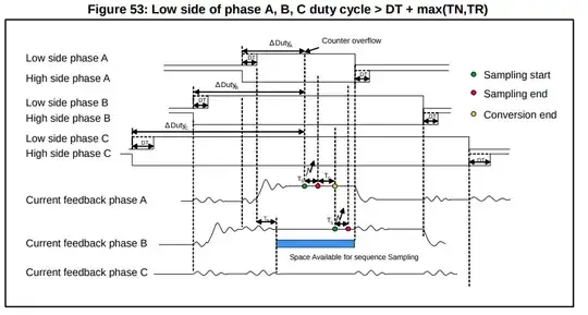
I am working on the implementation of an FOC controller for a BLDC motor and I am confused about the synchronisation I should perform between ADCs and PWM.
The setup implements 3 leg low-side measurement of the BLDC currents.
As I want to implement an FOC algorithm, I would need to compute the 3 inline current as feedback to my controller ia, ib, ic.
With my setup, I can only measure the 3 low-side current i'a, i'b, i'c.
To avoid confusion, I think it is important to precise that:
ia + ib + ic = 0 (inline)
but
i'a + i'b + i'c = I_DC (low-side)
I have read in the STM documentation that the low-side current sensing should be synchronized with the period when all 3 low-side gate are closed as shown in the figure below:
My questions are the following:
- Why should we measure at this particular time as this represents an open circuit with 3 high-side gates open, 3 low-side gates open, no current?
- In the figure above, they only measure i'a and i'b so how do they compute i'c since i'c = I_DC - i'a -i'b
- Finally, as an open question: assuming that my PWM frequency is around 20 to 30kHz, what should be the order of magnitude of my current control loop frequency and consequently, the frequency of the ADC sampling synchronized with the PWM?
