2

I am trying to use two G5V-2-DC5‎ relays to switch four wires at the same time between two different outputs. All signals are 5 V. I've gotten this to work fine with a simple physical switch but want to trigger the relays from another circuit. Wiring the + side of the relay trigger to the input directly doesn't work. I've also tried putting a 2N2222 transistor in, triggered by the input with the collector wired to the positive rail but the emitter ends up with a voltage too low to trigger the relays.

I vaguely realize that there are usually resistors in a circuit (such as with an LED to restrict current) but any time I've put a resistor in this circuit the relays don't trigger. I could use some guidance on how to make this work.

The relay pins (4-13) connections are not shown in the below schematic. While they are wired they are part of a separate circuit. There are 2 relays wired in parallel which work properly and draw about 220 mA when pin 1 is wired directly to the +5 V rail via a physical switch.
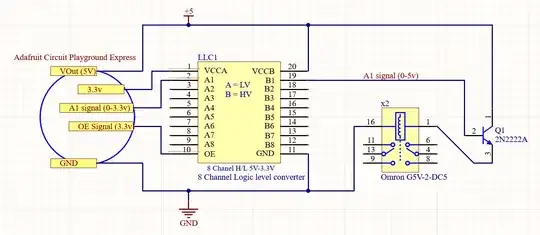
circuit diagram

Null
  • 7,448
  • 17
  • 36
  • 48
papercrane
  • 151
  • 5
  • 3
    Draw and show a schematic of what you've done so far. – Klas-Kenny Jan 25 '22 at 20:27
  • 1
    This seems like a common collector buffer which won't do what you want - please look at https://electronics.stackexchange.com/a/105866/9612 and let us know if it happens to answer your question. – nanofarad Jan 25 '22 at 20:30
  • 1
    You also need to show what the "input" is. I would guess it isn't strong enough to drive the relay (which requires on the order of 100 mA), which is why you tried the transistor, but we need to know. – Null Jan 25 '22 at 20:30
  • 1
    Sounds like you have the NPN transistor wired backwards. And the resistors for the transistor base is as much for protection of the transistor as it is to male it work. Add a schematic of what you have wired and we can tell you how to fix it. – Passerby Jan 25 '22 at 20:39
  • 2
    Does this answer your question? [Why load in NPN transistor switch are located in collector circuit?](https://electronics.stackexchange.com/questions/219324/why-load-in-npn-transistor-switch-are-located-in-collector-circuit) – brhans Jan 25 '22 at 21:13
  • It looks like I may have the transistor on the wrong side of the relay. I'll try swapping it. – papercrane Jan 25 '22 at 22:04
  • The NPN has to go on the low side of the relay. You should put at least a current limit resistor in the base path. See the answer here: https://electronics.stackexchange.com/questions/166670/how-do-i-energize-a-12v-relay-coil-using-a-2n2222-bipolar-transistor. Also consider adding a protection diode to absorb voltage spikes generated by the relay coil. – SystemTheory Jan 25 '22 at 22:49

1 Answers1

3

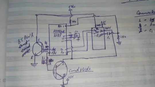
Thanks to the comments on my post I found my answer. The transistor needed to be wired to the GND end of the relays rather than the 5v side. circuit diagram

papercrane
  • 151
  • 5
  • 2
    Don't forget the diode. Special effects are very visual without it. – TQQQ Jan 25 '22 at 23:53
  • And thanks to other answers I realized that the level shifter was also not needed in this configuration. – papercrane Jan 26 '22 at 00:12
  • 1
    Added a diode in reverse across the relays as suggested as well as a resistor on the base of the transistor. – papercrane Jan 26 '22 at 00:19
  • 2
    TQQQ is right, there needs to be a diode across the coils [https://www.allaboutcircuits.com/textbook/semiconductors/chpt-3/inductor-commutating-circuits/] , to suppress the large voltage spikes that occur when the relay switches off. Also you must protect the base of the transistor with a resistor (try 1kΩ), to prevent excessive current flowing into the base when the control signal is above 0.7V. – Simon Fitch Jan 26 '22 at 00:19