5

So I'm looking to install an aftermarket seat heater in my car (though this would be useful for many other automotive applications). The switch it comes with does not reset on power loss, so if you leave it on, and turn off the car, when you return to your car and turn it back on, you'll slowly start to notice your ass getting warm...

I've tried to look for a switch that just bounces back to the center when power is lost (the switch must be 2 positions, with 12v in, ground, and two switched pins one for LO and one for HI) but I can't for the life of me find one. I'm also not sure how I would go about wiring something up to make it so that the switch must be powered off and then back on to regain power after power loss, though I'm thinking that might be possible with NO relays or something, based on what I have read.

Also it would be nice if the switch wasn't ugly and had the option of being backlit, since this is an automotive application after all.

For reference, the aftermarket heater I'd like to use is this one, and an image of its wiring diagram is attached. wiring diagram for aftermarket seat heater

  • 1
    Maybe doesn't help very much, but I don't think I've ever had a car that turns off the seat heater when the car is turned off. It starts back up when the car is started again. Some with mechanical buttons making it harder to do the auto-off, but same with more modern cars that have soft buttons. – Klas-Kenny Jan 24 '22 at 06:24
  • Thomas. Do I have it right that the product's BACK and CUSHION elements are completely independent and you can throw away all the wiring and relay stuff they may include with it? You are open to replacing what's needed and just hooking up the BACK and CUSHION elements, as then needed, should a workable design be proposed? – jonk Jan 24 '22 at 07:20
  • Note that the switch in the schematic connects power to HI for back and cushion, and both HI and LO for just cushion . Bother heater elements get power through HI, and then LO activates a relay that disconnects ground from one coil. They are probably using a DPDT center off switch for this with the throws on one side connected together. If so, I think it could be rewired to eliminate the relay and cut the current the HI contact has to carry in half. I'm not sure why they would do it this way, maybe the lights? I'd have to know the exact type of switch it is to be sure. – GodJihyo Jan 24 '22 at 07:25
  • @Klas-Kenny This may be true for some cars, but none that I've ever driven. I have a Chrysler 300c, my mom has a Dodge Journey, my dad has a Hyundai Santa Fe and my last car was a Chrysler 300m, and all of those cars reset the heated seats when they're power cycled. I'm sure there are some cars which use a physical switch which means they can't, but all the cars I've driven with soft buttons reset their state. Either way, I'd like to have that functionality. – Thomas Sebestyen Jan 24 '22 at 18:23
  • @jonk Yes, you do have that right indeed, it comes with all the wiring necessary to use them, but I could easily splice in whatever the heck other crap I want to. – Thomas Sebestyen Jan 24 '22 at 18:23
  • @GodJihyo I believe they did it this way because it's simpler. I would be willing to do some more advanced current-limiting stuff if it's not too expensive. The switch has a yellow and red light for each state. There are better photos of it on the Amazon page. However, like I said in the previous comment, I could easily throw this all out and wire up my own thing, this is just the stuff that's included with the kit. – Thomas Sebestyen Jan 24 '22 at 18:25
  • @ThomasSebestyen I guess the first thing that comes to mind is a center-off *momentary* rocker switch. This can only be momentarily in the other two positions and always returns to the center position when released. It can easily then use existing power (if the vehicle is on) to latch relays to arrange any setup you want for either momentary-on position. When the vehicle is switched off, the power is removed from the relays and they return to their off condition for whatever they control. (The active relays won't draw significant power compared to the heaters they operate.) – jonk Jan 25 '22 at 06:02
  • @jonk that sounds like it would be perfect for this application. Would you be able to help me with a wiring diagram? Or a reference to somewhere that explains it in more detail? Thank you – Thomas Sebestyen Jan 27 '22 at 23:15
  • @godjihyo no, the low causes the 12V to go through the back and cushion, halving the voltage on both. Hence the low vs high. That's typical. – Passerby Jan 28 '22 at 23:23
  • @Passerby Ah, I see it now.. because of the way it's drawn I totally missed 87 on the relay. – GodJihyo Jan 29 '22 at 03:36
  • @godjihyo yeah it's a bit complicated. – Passerby Jan 29 '22 at 05:45

1 Answers1

10

First off, you may want to select a switch that provides tactile and visual cues that make sense to you. I'll provide two examples:

In the latter case, not listed in the datasheet there but available, is the TJ mounting frame which includes two LEDs you can use, if you want that.

Regardless, once you've selected the switch it is just a matter of finding two relays that are DPDT (double-pole, double-throw) devices:

schematic

simulate this circuit – Schematic created using CircuitLab

Above, the LO and HI switches shown are really just two parts the same switch: one of them being one side of one pole, the other of them being the other side of the other pole. It isn't possible for you to turn both of them ON at the same time because of the switch design, so the above circuit doesn't protect against that impossibility.

I just threw this together between bouts of sleep, so I will check this over better tomorrow. But I figured I'd put it out there for your consideration and to allow others to check the work and complain, if they see a problem above.


New day.

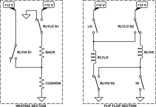
The earlier schematic was more of a wiring diagram. The following is more of a conceptual (for purposes of understanding it) diagram:

schematic

simulate this circuit

(When reading this one, keep in mind that both relays cannot be simultaneously activated. Also, I removed the two diodes to aid clarity.)

On the left side, when both relays are inactive then both sides of the BACK and CUSHION heaters are grounded and the middle node is left floating. So no power is applied to them and they are galvanically tied at both ends to the vehicle's ground.

When the LO relay is active, then the BACK and CUSHION heaters are connected in series between \$+12\:\text{V}\$ and the vehicle ground, so that they present a high impedance and therefore lower power is applied to them, as is appropriate in this case.

When the HI relay is active, then the BACK and CUSHION heaters are connected in parallel, applying \$+12\:\text{V}\$ to the center node while both opposing ends are at the vehicle ground, so that they present a combined low impedance and therefore higher power is applied to them, as is again appropriate in this other case.

The right side has three states:

  • Both relays OFF: In this state, the LO relay is tied at one end (through the inactive \$S_2\$ state of the HI relay) to the vehicle ground. Meanwhile, the LO momentary switch tied to \$+12\:\text{V}\$ so that, when pressed momentarily, it can actively supply power to the LO relay. Similarly, the HI relay is tied at one end (through the inactive \$S_2\$ state of the LO relay) to \$+12\:\text{V}\$. Meanwhile, the HI switch is tied to the vehicle ground so that, when pressed momentarily, it can actively supply power to the HI relay. In short, either relay can be activated, depending on which way the HI/LO momentary DPST switch is pressed.
  • LO relay is ON: In this state, power is continuously supplied to the LO relay via \$S_2\$ of both relays. The momentary switch can return to its center position and the LO relay remains powered.
  • HI relay is ON: In this state, power is continuously supplied to the HI relay via \$S_2\$ of both relays. The momentary switch can return to its center position and the HI relay remains powered.

When vehicle power is removed, both relays also become unpowered and the system returns to its unpowered state where it will remain when vehicle power is returned and the circuit can be used again.

Hopefully, that helps clarify the design a bit.

The idea is missing one detail. Once LO is activated, the HI mode is unavailable. Similarly, once HI is activated, the LO mode is unavailable. (By design. I intended it when I was laying this out.) A simple solution I'd considered is to add a series momentary SPST (normally closed) between the actual vehicle \$+12\:\text{V}\$ and the \$+12\:\text{V}\$ rail used in the flip-flop portion of the circuit. Pressing the button would open this switch, releasing the relays and returning the rocker switch to select a new mode, if desired.

If you want that feature, add the normally-closed momentary SPST RESET switch as shown at the top of the schematic below:

schematic

simulate this circuit

That will emulate the effect of turning the vehicle off, resetting both relays.

Don't forget the fuse that was indicated in your original schematic!

jonk
  • 77,059
  • 6
  • 73
  • 185
  • Great answer! I would include that reset switch regardless because otherwise you have to turn off the car to turn the seats off. – Passerby Jan 28 '22 at 23:31
  • 1
    @Passerby Hehe. I was kind of hoping I could keep things just as a final footnote. But I guess that makes sense. I can add a bottom schematic, I guess. ;) – jonk Jan 28 '22 at 23:35
  • 1
    This is AMAZING, @jonk thank you SO much for this! Can't wait to wire it up and see how it works! Just gotta find some nice looking switches now! – Thomas Sebestyen Jan 31 '22 at 03:46
  • I may consider using a 3 position momentary switch if I can find one, and wire the center position as the OFF/RESET switch. – Thomas Sebestyen Jan 31 '22 at 03:52
  • @ThomasSebestyen Hope things work out well. This should work out fine. It might be possible to redesign this so that the RESET switch isn't needed. But it requires a special kind of rocker switch that may be difficult to find. So I avoided that. If you want to see the diagram for that kind of weird rocker (which I don't know where to find) then I could diagram that, as well. It would remove the need for RESET. I just don't know where to find one of those kinds of rocker switches. – jonk Jan 31 '22 at 03:53