Without knowing more about the various grounds running around, this sounds like a three circuit problem: The AC being sensed, the DC being sensed, and the power source for the beeper.
I would use two opto-isolators, one for the AC input and one for the DC input, with the two output transistors in series with a loud piezo beeper and its supply. No logic chips, no opamps or comparators, no Arduino, and no 555's. <gasp!>
The DC input needs a current limiting resistor, and I would add a small bridge rectifier so the input polarity doesn't matter. The AC input needs a current-limiting capacitor, a rectifier, and a small filter capacitor so there is a constant DC through the opto's input LED.
Power quality on a boat is very poor. A Zener diode in series with each opto input will increase noise immunity.
If the 12 Vdc power source for the beeper is the same as the one being sensed, I'd stay with the optoisolator. It's actually less messy than sensing the 12 V with a transistor or comparator.
I can whip up a simple schematic if you need one, and add it to this response. Or you can take a swing at one and we will advise.
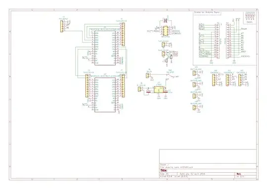
UPDATE - Schematic
Here is a first-pass at a schematic. I came to my senses, and replaced a bunch of semi-dangerous stuff with an off-the-shelf 12 V wall wart. It is a cheap way to get certified isolation, noise filtering, and safety.
A range of component values will work for the resistors and Zener diode. The only real requirement is that the piezo beeper current be less than 20 mA to limit the current through the LED. Without the LED, the piezo current can be higher. The opto-isolator output transistor is rated for 50 mA, but I wouldn't run it at that level continuously.
Note: Both 12 V inputs are polarity-sensitive.
Note: There is no GND symbol in the schematic. I did this on purpose. All three circuits are completely floating with respect to each other.