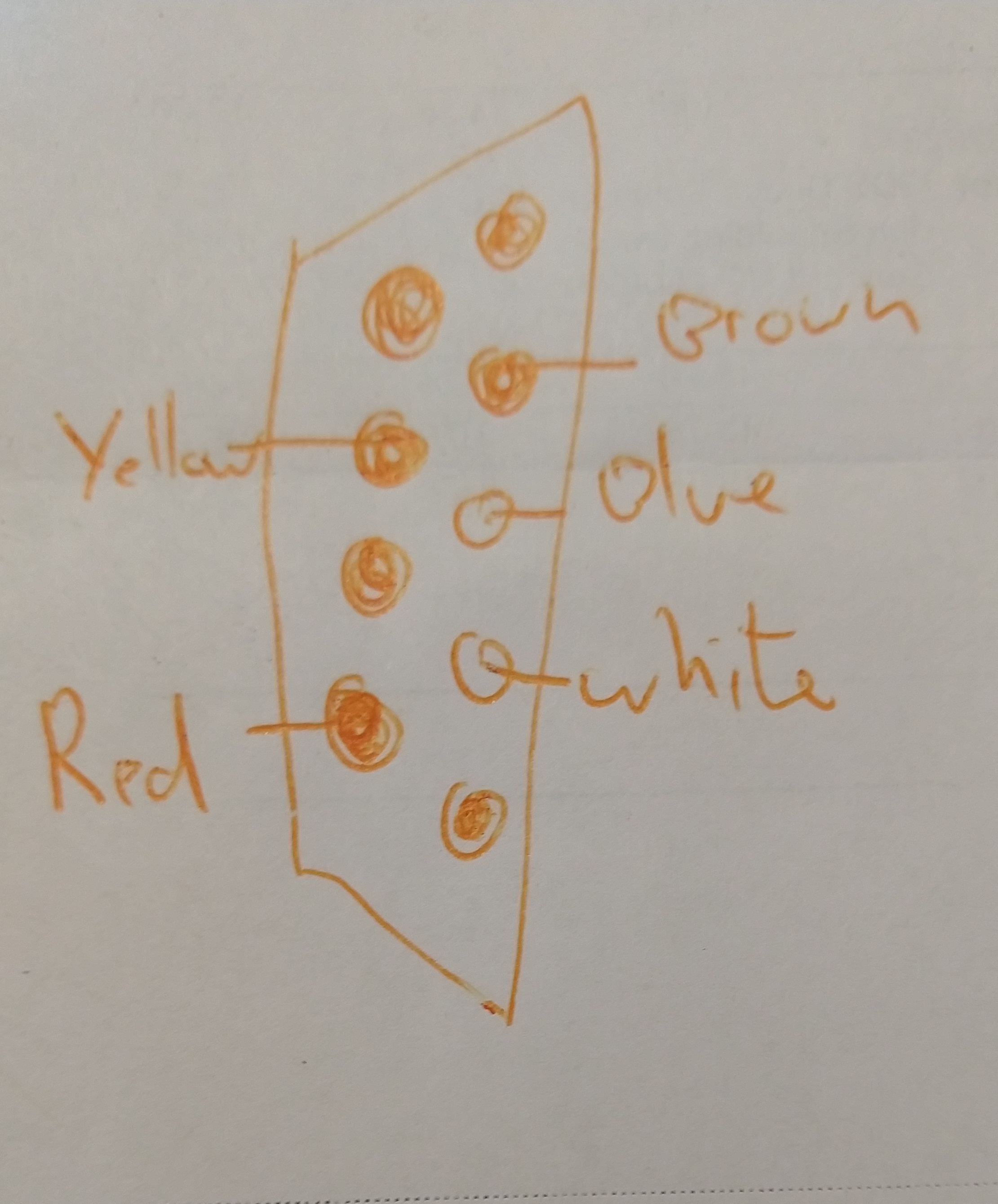
I have an old game console which had Mario and contra old games . It has two controllers,they have db 9 female at there end but i want it to run it in my PC via USB. I want to know how i can convert the DE-9 female to USB at home i also have Arduino Uno if needed. And one issue is the DE-9 connector has 9 pins but only 5 wires are coming out from my controller. My controller has 5 wires white wire is +5 volts, blue is clock, yellow is latch, red is data, and brown is ground. These 5 wires are only wired in the DE-9 female port like the image here https://www.summet.com/blog/wp-content/uploads/2019/03/nes_controller_pinout.jpg
Asked
Active
Viewed 130 times
0
-
these are the images https://ibb.co/qNtwzcz https://ibb.co/KwdnnvD – RobinHoodRKA Jan 22 '22 at 07:42
-
2the images belong in the question, not in comments ... ... do not insert links, use the `add picture` button – jsotola Jan 22 '22 at 09:01
-
You can buy these kinds of a adapters off the shelf pretty easily – Ryan Jan 22 '22 at 14:01
-
@Ryan The issue is you can't buy an adapter until you know what adapter to buy. – Peter Green Jan 24 '22 at 23:30
-
1Jumping to conclusions about the electrical interface based on the connector is a dangerous way to go. We already had one (now-deleted) answer here that assumed DB9 meant RS232 serial, that's a particularly risky assumption because RS232 uses relatively high voltages. – Peter Green Jan 24 '22 at 23:43
1 Answers
1
It's certainly possible to build circuits to adapt retro game controllers to USB, but first you need to figure out what it is you actually have. "DB9" (strictly DE9 but everyone calls it DB9) is a generic connector used for many different interfaces.
Mario and Contra were both NES games afaict, but the NES did not use the DB9 connector, so I would guess what you have is an unofficial NES clone. If so the controller may (or may not) be electrically a NES controller.
Can you open the controller and get any pictures of the circuitry inside?
From the pictures.
I see 5 wires, which is consistent with a NES style controller. Unfortunately the chip seems to be a "glop top" so following the traces probably isn't going to give us any clues as to which pin is which.
If you want to continue reverse engineering, the first thing to do is to try and figure out which lines are power and ground, there may be hints on the controller PCB like fatter traces, there may also be hints at the console end.
Then you have to try and figure out which signal line is which, it should be relatively easy to identify the different waveforms for the clock line, data line and latch control line on an oscilloscope, but I don't see a reasonable way to do it without one.
Another approach may be to google something like "nes clone DB9". Someone may have already reverse engineered it. I don't know to what extent there was a de-facto standard among NES clones though.
When I did so I found https://forums.nesdev.org/viewtopic.php?t=6236 which linked to http://davr.org/snes/joystick.txt which claims to have a pinout for a 9 pin NES clone. The comments in the nesdev thread however said the diagram was "backwards", so YMMV (though only 5 pins are used, so if there is a mirror image issue it should be easy to tell once you figure out with a multimeter which pins are wired up).
Peter Green
- 21,158
- 1
- 38
- 76
-
-
-
-
-
hey i found that in my controller white wire is +5 volts ,blue is clock ,yellow is latch,red is data and brown is ground. wire – RobinHoodRKA Jan 22 '22 at 09:55
-
these pins are wired up https://www.summet.com/blog/wp-content/uploads/2019/03/nes_controller_pinout.jpg – RobinHoodRKA Jan 22 '22 at 09:57
-
these pins are wired up https://www.summet.com/blog/wp-content/uploads/2019/03/nes_controller_pinout.jpg this is link to image – RobinHoodRKA Jan 22 '22 at 10:17
-
-
Ultimately you are the one who has the controller, not me. I don't have any real way to confirm or refute your discoveries from here. Driving a nes style controller from a microcontroller should be pretty easy, it's just a shift register. – Peter Green Jan 22 '22 at 13:30