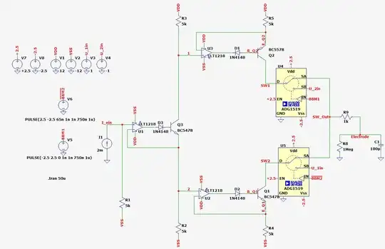
In this simulation the circuit generates a AC signal at "Electrode". Here I am using two SPDT-Switches (Ron = 4 Ω).
My first question: Why isn't the signal correctly rectangular? And how can I correct that?
On the second circuit I am replacing the ideal current generators with current sources:
My second question: Why aren't the signals at "sw1" and "sw2" constant over time and why don't they have a similar value as in the first simulation? And how can I correct that? Or which circuit mirror implementation should I use instead?
I tried to plot the signals, which may be needed for the interpretation.
