1

I have an ±15 V AC output that needs to be level-shifted to 0-1.2 V level to be read by a microcontroller ADC input. It needs a rather decent resolution so that the ADC can be quite accurate.

My circuit only has a 3.3 V supply.

What's the best way to achieve this?

  • The input is actually ± 15 V AC sine wave from a three-phase alternator with frequency ranging from 100 Hz to 2000 Hz.
  • I am designing a three-phase synchronous rectifier. I compare the voltage levels of each phase of the input to get the timing for the three-phase MOSFET bridge rectifier switching.
  • So far I am a bit successful by using a rudimentary resistor divider to level-shift the ± 15 V input to 0-1.2 V as I can use the positive-half of the sine wave at low frequency.
  • My intention is to get robust level-shifted inputs so that the signal doesn't get attenuated across low to high frequency.
Null
  • 7,448
  • 17
  • 36
  • 48
  • 1
    Does this answer your question? [Negative Voltage Level Shifting to an ADC](https://electronics.stackexchange.com/questions/56324/negative-voltage-level-shifting-to-an-adc) – devnull Jan 14 '22 at 11:27
  • 1
    What is the frequency? – bobflux Jan 14 '22 at 11:32
  • Please specify ADC input impedance and the resolution requirement. – tobalt Jan 14 '22 at 12:51
  • 2
    Does this answer your question? [Analog voltage level conversion (level shift)](https://electronics.stackexchange.com/questions/30719/analog-voltage-level-conversion-level-shift) – tobalt Jan 14 '22 at 12:53
  • 1
    Do you want to level shift an instantaneous +15V to 1.2V and an instantaneous -15V to 0V? Or do you want a sine wave input of 15V peak converted to a constant 1.2V output? – Math Keeps Me Busy Jan 14 '22 at 13:49
  • 1
    Please describe in more detail what the signal is, where it comes from and what you expect to do with it. – Kevin White Jan 14 '22 at 17:04
  • 1
    @bobflux The frequency range is 100 - 2000Hz. I've added more details to the post. – scvgoodtogo Jan 15 '22 at 12:42
  • 1
    @MathKeepsMeBusy I want to convert a ± 15V sine wave to 0-1.2V sine wave. Basically just level-shift the signal while keeping the frequency to be the same. – scvgoodtogo Jan 15 '22 at 12:42
  • @KevinWhite I've edited the original post with more details. – scvgoodtogo Jan 15 '22 at 12:42
  • @tobalt ADC input impedance is in the range of gigaohms and resolution is at least 1mV – scvgoodtogo Jan 15 '22 at 12:43
  • 1
    If the goal is to drive a three phase rectifier, why not just use a bunch of comparators? – bobflux Jan 15 '22 at 12:50
  • 1
    @bobflux You're right, I have considered using comparators before. I am thinking of some cost savings by using low-cost opamps in combination with the microcontroller. But based on the answer given below, it seems like using a medium-voltage comparator would be the better choice. – scvgoodtogo Jan 15 '22 at 13:05
  • 1
    There's also the problem of sample rate, if your AC is 1kHz the ADC would have to run at very high sample rate on 3 channels to spot the crossings accurately. And LM339 isn't really expensive... – bobflux Jan 15 '22 at 13:33

4 Answers4

5

enter image description here

Hi,

We want to convert single-ended bipolar to single-ended unipolar to feed the ADC. This can be done by attenuating the input signal while also adding a DC offset equal to half of the adc reference voltage. This way the original signal will swing around the mid-point of your ADC's input range in attenuated form.

I assume the ADC has a full scale range of 1,2V. We find both the positive and negative swing of the input signal equally important, so we offset the signal to 0.6V. You can just generate this voltage any way you like. It is more accurate to take this potential directly from the adc by dividing the reference voltage. A good converter IC usually has this available. If it is perhaps build into an uC that has no pins for analog reference, just take the AVDD and AVCC signals instead.

I selected TLV9002 for this. It's low cost and has reasonable specs for general purpose applications. If you are after precision, definitely get a better amplifier. Its inputs and outputs needs some headroom from the supplies to work. So instead of a 1/25 gain I chose 1/30 gain to match the signal to the adc, this way we leave 100mV on both ends of the signal.

I added a bi-directional Zener to protect the input. I’m not sure what you are measuring. The resistor is there to protect in combination with the Zener. This resistor is added on the grounded side of the input as well, in order to keep it balanced. The gain is going to be off by a bit though, if that’s a problem then lower this series protection resistor or account for it with the gain setting. I selected the resistors based on calculation, find some values that are appropriate for ordering and your circuit

Now this output signal can be fed to your ADC. It will always be biased exactly to mid-range (with small offsets)

Thijs
  • 604
  • 2
  • 7
  • Thanks for the detailed circuit and explanation. As I would understand it, U1_A is in differential amplifier mode. Thus, wouldn't Vout be inverted as compared to VIN based on the formula of Vout = [R4/(R3+R4)]*[1+R2/R1]*Vref - [R2/R1]*VIN where R1=R4=100.1k and R2=R3=3.33k? For example, when VIN=+15V the resulting Vout=0V, while VIN=-15V the resulting Vout=1.1V. – scvgoodtogo Jan 19 '22 at 08:06
  • Hi, no worries glad to help. Yes now you mention it I hooked up the signal to the negative input of the differential amplifier, so the signal is indeed inverted. I'll edit this for correctness. Either swap the inputs or you could also try some tricks in firmware. As for the gain, this output amplitude should be 0.6V +- 499mV for +-15Vin, when working with 1.2Vref. It should not go to 0V output, because no opamp can output exactly 0V on a single supply. Rail to rail opamps can get close, but AC performance takes a hit. Thats why the gain is set to this level – Thijs Jan 19 '22 at 10:10
2

As you wrote that your ADC input impedance is high (Gigaohm), you can use a simple 3-resistor voltage translator, to get an accurate, linear, passive voltage level translation (that also protects your ADC input):

+15..-15 V input to 0..1.2 V output

schematic

simulate this circuit – Schematic created using CircuitLab

Here is an excellent breakdown of how to calculate the values by user @jonk.

tobalt
  • 18,646
  • 16
  • 73
0

Level Shifter + & - 15 V to 0 - 1.2 V

Level Shifter

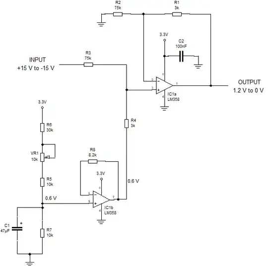
IC1a, although it could be described as being configured as a non-inverting summing amp, I would prefer to refer to it as being configured as a differencing amplifier with one input having the input signal applied to it and the other input tied to ground (into R2). The reference voltage for this differencing amplifier is held at a constant 0.6 V.

The gain of the differencing amp (IC1a) must be equal to :-

(Vout pk to pk)/(Vin pk to pk) = 1.2/30 = R1/R2 = R4/R3 = 1/25 = 3k/75k

I have found out, by playing with these circuits over the years, that to get a certain output swing for a certain input swing that R2 (the inverting input) needs to be connected to the mid-range of the input swing (0V in this case) and that R4 (the reference) needs to be connected to the mid-range of the output voltage swing (0.6 V in this case).

The 0.6V reference is generated by a resistive divider consisting of R5, R6, R7 & VR1. VR1 would need to be set to a value of approximately 5k to provide the 0.6 V reference. This 0.6 V reference is filtered from power rail noise by C1 and buffered by IC1b. The buffer is necessary to prevent the voltage genereted by the resistive divider being affected by the load of R3 & R4. The potentiometer, VR1 is included in the design so as to be able to compensate for (when setting the 0.6 V reference voltage) any inaccuracy in the 3.3 V supply voltage

R8 is equal to the parallel combination of (R5+R6+VR1)//R7 and is included to remove offset at the output of IC1b which could otherwise be caused by IC1b's input bias currents.

The output of a LM358 will not swing quite as low as 0V (when the negative rail is 0V) but it will get pretty close to it.

Finally it's a matter of consulting the LM358's data sheet and checking the design to make sure that the common mode input range is not violated and that IC1a's inputs do not swing beyond the maximum allowed negative voltage. Also need to check that, when considering the output's positive saturation voltage, that there is enough headroom with a +1.2 V output.

  • OP, have a look at "Analog Engineer's Circuit Cookbook: Op Amps". Thats a pdf file that has some circuits and what you need is "Inverting Op Amp With Non-Inverting Positive Reference Voltage Circuit" which is the circuit in the answer. You can find it on google. – Hedgehog Jan 15 '22 at 14:35
-1

As OP added more information and wants output to be a sine wave this answer is not correct. Not sure if I should delete it or leave it be

Assuming you have a sine wave. Then, negative part can be ignored. Try this and see how it works. It's a peak detector circuit. Diode is used to pass positive voltage, capacitors are then charged and disharged by resistors.You would have to calculate values by yourself since your question is quite vague.

Circuit

Here are some simulations enter image description here

enter image description here

Hedgehog
  • 94
  • 10
  • The OP didn't ask about a peak detector but about a signal level shifter. Also when loaded with the ADC, your circuit output would change considerably. – tobalt Jan 14 '22 at 12:49
  • @tobalt The op vaguely asked for ± 15V to 0-1.2V voltage conversion. This does that. Like I said, "Assuming you have a sine wave", peak detector is fine. Post a better question get a better answer. Let's see your answer tobalt. – Hedgehog Jan 14 '22 at 12:57
  • @tobalt About loading, connect a buffer. – Hedgehog Jan 14 '22 at 12:59
  • @Hedgehog yes, it does shift the voltage but, if the OP has a 0-15vac signal, it is likely audio frequencies. Also, you got it only half correct, because you elected to ignore the negative half wave. What is the frequency response of your circuit (answer is "not good"). – GT Electronics Jan 14 '22 at 13:47
  • @GTElectronics "it is likely audio frequencies" question does not say that. I assumed it wasn't and gave this answer. Like I said, post a better question get a better answer. This does what the title says with information provided. – Hedgehog Jan 14 '22 at 14:08
  • 1
    I retract my downvote as the question could be indeed interpreted in this way. Btw my "answer" in comments to the OP was seemingly deleted without clarification what was the issue. – tobalt Jan 14 '22 at 14:46