3

There's an AC signal, 1 V amplitude, which is the input to an op-amp, in differential mode:

figure 1

However, the output gets clipped and the amplitude isn't unity for some reason, even though gain is set to be 1.

figure 2

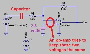
To "fix" this clipping, one needs to "bias" the op-amp by putting a reference midpoint (resistor divider network for example) at the positive terminal of op-amp, like this:

figure 3

An "explanation" is that:

for the opamp to swing high, your input signal has to go below the ground, so you set up "virtual ground" somewhere between rails so that your opamp has some reference against which to invert the input signal

Or the "op-amp can't go beyond its output rails" etc. These explanations do not help me understand the why.

To understand why, I'd like to know how the output of the OP284 changes with changing inputs to the OP284.

Is this approximately what the OP284 looks like?

figure 4

Let's assume it is, which is just a bunch of BJTs.

V1 = negative terminal input to U1 V2 = positive terminal input to U1.

Output of U1 is: \$ V_{out} = Gain * (V_2- V1) \$

Gain is unity, so it's just: \$(V_2- V1)\$

Let's assume V5 (input source AC signal) goes like this:

At t = 1, Vin (positive terminal of V5) -> V1 is 0.1 V, V2 = 0 V.
t = 2, Vin = 0.2 V, V2 = 0 V
t = 3, Vin = 0.3 V, V2 = 0 V

For these three time instances, what's Vout?

Well, from figure 4, Q2 is closed off pretty much all the time, right? Q1 is slightly on, so Vo1 is about 0.1 V, while Vo2 is the maximum 5 V? (VCC5 rail).

So what about Vout when:

t = 10, Vin = 1 V, V2 = 0 V
t = 11, Vin = 0.9 V, V2 = 0 V.
...
t = 20, Vin = 0 V, V2 = 0 V
t = 21, Vin = -0.1 V, V2 = 0 V

?
ocrdu
  • 8,705
  • 21
  • 30
  • 42
user234571
  • 45
  • 5
  • 3
    A very simple answer is that there is nothing inside of an opamp that can generate new voltages, just resistors and transistors that can switch and divide the voltage that you provide. By raising your signal to be above your negative rail and below your positive rail, you hopefully avoid trying to produce voltages outside of that range (at least if your input signal amplitude doesn't get too large). – user1850479 Jan 12 '22 at 05:13
  • So is the question about why an op-amp, or any circuit, can't output voltages that are beyond the supply voltages? – Justme Jan 12 '22 at 05:17
  • @user1850479 how am I "raising" my signal above my negative rail???? Input source AC signal swings fine between +1V and -1V, and I give to op-amp +5V and the same -1V for the negative supply. So the negative supply side of U1 is same node as negative source terminal V5. – user234571 Jan 12 '22 at 05:27
  • @Justme the questions have question marks in them – user234571 Jan 12 '22 at 05:29
  • The input signal to the opamp in your second diagram has no negative voltages at all, the addition of the positive voltage to the input raises it above zero so everything is positive. Since you got rid of the negative voltages, you don't clip. – user1850479 Jan 12 '22 at 05:34
  • @user1850479 what do you mean, V2 has no negative voltages? V1 and V2 switch polarities, so if you're measuring V1 with respect to V2 you can get -1V. – user234571 Jan 12 '22 at 06:27
  • Very simple ! in order for the output to be in the middle of the linear range , both inputs MUST BE AT THE SAME VOLTAGE. Its' called a virtual null or error amplifier and if the average DC inputs are not the same, it won't work (saturate to one rail) It's doesn't matter if you follow the input voltage on Vin+ or use a fixed Vin+ = Vref and using the inverting input.. the two inputs must be the same voltage. somehow. in the acceptable Common mode input range – Tony Stewart EE75 Jan 12 '22 at 07:00
  • both inputs can become the same, have you looked at the input source graph on figure 1? Vin = V1 = 0, V2=0, that's when. – user234571 Jan 12 '22 at 08:35
  • You probably figured this out already, but since you add 2.5v to a signal that had a minimum of -1V, then new minimum is 1.5V which is clearly nonnegative. Hence, no clipping. – user1850479 Jan 12 '22 at 18:15
  • I think what you want your opamp to be is actually a different circuit/building block. Which is called an instrumentation amplifier. – rackandboneman Jan 12 '22 at 18:40

2 Answers2

7

Why does differential op-amp require mid point biasing at its input to prevent clipping?

It's not just a differential op-amp circuit, it's any linear op-amp circuit...

So, you are confusing yourself by not recognizing the basic problem. The confusion arises because you have chosen an overcomplicated circuit to learn a very basic thing: -

enter image description here

The above is not a differential op-amp; it's a single-ended input and the op-amp's negative rail is at ground potential. It's an inverting amplifier with a gain of unity; virtually as simple as it gets.

So, when the input signal goes below 0 volts, in order to keep Vin- at the same value as Vin+ (which happens to be 0 volts), the op-amp output rises to a positive value. That positive value enforces Vin- == Vin+. Not a millivolt higher nor a millivolt lower; that's what the op-amp is conditioned to do; it must makes Vin- == Vin+.

It has no other task.

However, if the input signal has a positive value then the op-amp output cannot make its output go below 0 volts and thus it clips. The output is limited to values within its power supply range; some are better and some are worse of course.

However, the output gets clipped and the amplitude isn't unity for some reason, even though gain is set up to be 1.

No, of course it isn't unity; it's clipped; it's shortened; it's reduced.

To understand why, I'd like to know how output of OP284 changes with changing inputs

It's got nothing to do with the op-amp model number; all op-amps will do the same.


Back to the basic circuit but with an input capacitor

enter image description here

It's a the same story; the op-amp can't fight against the input signal rising positively above 0 volts but, because we have added a capacitor there's a chance we can shift the output up a few volts and avoid it clipping: -

enter image description here

So now, the op-amp has a fight it can win; it's trying to make Vin- have a DC value of +2.5 volts; the op-amp can pull and push that voltage around by moving its output towards the positive supply rail or by moving towards ground. It's a symmetrical situation and, unless the input has an amplitude that is close to and beyond the power rails, the op-amp will produce a relatively undistorted output signal.

Andy aka
  • 434,556
  • 28
  • 351
  • 777
  • >"When the input signal goes below 0 volts." Before that, I'd assume the positive rail of V5 was positive, and the negative rail, well at 0V, which is a reference point for everything aka "gnd". So when Vin, with respect to GND (which is also the positive terminal input to op-amp) becomes 0, and then current direction changes, and V5 source's polarity changes, thus "GND" rail becomes positive and Vin side negative, right? Is this the moment you're talking about. – user234571 Jan 12 '22 at 08:40
  • 1
    Try and order your thoughts and speak in simpler sentences. What you wrote in your comment is far too loaded for me to unpick. Assume the input signal peaks at +1 volt and -1 volt - don't overcomplicate things with it having a peak value that equals the op-amp power rail. – Andy aka Jan 12 '22 at 08:44
  • Here's circuit with labeled nodes: https://i.imgur.com/o54Y6dK.jpg. It's comment section, so have to make it short not detailed, but I'll try. "When the input signal goes below 0 volts, in order to keep Vin- the same as Vin+, the op-amp output rises positively." How does input signal go below "0V"? Vin1 starts out positive, rises, then decreases, this is all with respect to Vin2(gnd). When Vin1 =0V with respect to Vin2, Vin2 becomes positive and Vin1 is now negative (current direction change). But I think that the supply rails for OP-amp are fixed (VCC5 and Vin2/GND) and can't be swapped. 1/2 – user234571 Jan 12 '22 at 08:50
  • But if you do swap, then op-amp would be able to output the input signal, right? Like when Vin1 is -1V with respect to Vin2, and U1's negative supply side is connected to Vin1? 2/2 – user234571 Jan 12 '22 at 08:51
  • 2
    `How does input signal go below "0V"?` the input signal is a sinewave hence it goes positive then negative etc.. Just ask one question at a time because you are building on ideas that might be wrong. One question at a time please. Don't overload a comment with too much info because it won't work. – Andy aka Jan 12 '22 at 08:56
  • Here's one question. https://i.imgur.com/o54Y6dK.jpg Assume V5 starts out positive. When Vin1 is about +0.5V with respect to Vin2 (which is also GND), V1 (negative input to op-amp) sees positive voltage, which is I guess is about +0.5V with respect to Vin2? – user234571 Jan 12 '22 at 09:37
  • @Andy aka Upvote for a nice explanation in non-technical terms - one of the best I've seen. I've lost count of the times I had to do the same when I was an application engineer with National. – user131342 Jan 12 '22 at 09:54
  • @user234571 - the op-amp tries to produce a negative output voltage but it can't so, the best it might do is produce 0 volts (a semi ideal case). Then, given that both resistors are 10 kohm, the voltage at Vin- has to be 0.25 volts due to the potential divider. – Andy aka Jan 12 '22 at 10:46
  • @Andyaka right on, I think this "Vout" trying to produce opposite voltage to V1 is found in the derivations of the gain, when doing loop equations, iirc. Are you sure that BJT differential figure isn't accurate to an op-amp? Does look similar to other ones found on the internet: https://sub.allaboutcircuits.com/images/05249.png I'd like to read up on how exactly Vout producing opposite voltage (related to BJT transistors within op-amp circuitry I suppose), instead of accepting this info as a given. – user234571 Jan 13 '22 at 03:10
  • @user234571 the inverting-circuit op-amp produces the opposite voltage in order to make Vin- the same voltage as Vin+. Fundamentally it's that and not loop equations that give you the gain figure. Concentrate on the fact that the op-amp is a control system trying to make the two input voltages equal. – Andy aka Jan 13 '22 at 08:03
  • @Andyaka I know, how does it do it though, has to be BJT related. – user234571 Jan 17 '22 at 10:34
  • @user234571 it could use MOSFETs or, if you really want to time travel, I'm sure implementations were made using tubes/valves. In other words, it's tech independent. Sure, most do use BJTs and, the use a differential pair but that is less important than understanding how negative feedback (and very high open-loop gain) causes the two inputs to be kept at virtually the same value. Maybe look at this picture: https://i.stack.imgur.com/LSSjd.png taken from [here](https://electronics.stackexchange.com/questions/305402/help-understanding-how-op-amps-work). – Andy aka Jan 17 '22 at 10:41
4

Is this how approximately OP284 looks like?

No. Your circuit won't work close to the negative rail because the input transistors don't get enough bias voltage, but it can work close to the positive supply rail.

The OP284 has rail-to-rail inputs and outputs. To handle signals close to the negative rail it has an inverted form of your circuit wired in parallel, with PNP input transistors. The outputs of the NPN and PNP circuits are then combined in the following stage. Here's the 'simplified' schematic:-

enter image description here

But you don't need to know all this. Just remember that input voltages must stay between Vcc and Vee for correct operation, and the output voltage is constrained between Vcc and Vee.

In your circuit where the non-inverting input is referenced to ground (via R4) an AC input signal goes below ground during negative half cycles. This violates the common mode input voltage range, but even if it didn't the output voltage cannot go below ground so the bottom half of the waveform must be clipped.

There are two obvious solutions to this problem:-

  1. Supply a negative voltage to Vee that exceeds the maximum negative voltage swing on +IN. The output will then swing below ground on negative halves of the AC signal.

  2. Bias +IN with a positive voltage so when the input goes negative the voltage at +IN is above ground (Vee). Since the DC gain of the op amp is 1 in this circuit, the output will be 'centered' at the bias voltage.

Bruce Abbott
  • 55,540
  • 1
  • 47
  • 89
  • Even if I connect negative terminal of V5 to U1's negative supply rail, making them the same node, there's still clipping: https://i.imgur.com/5dEBfTg.jpg Why can't output just simply repeat what the input is? I'm guessing the issue is that difference of inputs is outputted. I provided examples, and I still don't know how output behaves at t=10, Vin = 1V, V2=0V t=11, Vin=0.9V, V2=0V. ... t=20, Vin=0V, V2=0V t=21, Vin=-0.1V, V2=0V. Also I don't need output to go below "ground". Input source doesn't "go below" gnd to show -1V. – user234571 Jan 12 '22 at 06:30
  • Because the op amp is biased at 0V (ie. ground, through R4), so the output is centered on 0V and positive input signal on -IN will try to make the output go below ground - which it cannot do (unless Vee is negative). – Bruce Abbott Jan 12 '22 at 06:38
  • yeah I read all that already, I don't get it, I just need to know how output behaves at different time instances – user234571 Jan 12 '22 at 06:59
  • Not sure I can explain it any better. perhaps you should try just considering the voltage on each input and calculating what the output would be with an 'ideal' op amp. Then when the answer is a negative voltage (which is impossible)... – Bruce Abbott Jan 12 '22 at 07:14
  • I kinda tried in the op-post, but nobody commented about those time instances. – user234571 Jan 12 '22 at 08:57