2

In question Quality factor in arbitrary RLC resonance circuits, the OP asks about the Q of more complex circuits other than simple series or parallel RLC topologies. The responses I read, in particular the one by LvW made me wonder why it wasn't "ok" to employ various impedance transformations to reduce the circuit to either a parallel or series RLC, and then use the standard formulas for the respective circuit type.

For example, using his first circuit in his question and assuming a voltage source,

enter image description here

Can this circuit not be converted to an equivalent parallel circuit via source and impedance transformations for which Q can be calculated?

schematic

simulate this circuit – Schematic created using CircuitLab

$$Q=R\cdot \sqrt{\frac{C}{L}}\;,$$ where \$L=L2||L1p\$, \$C=C1\$, and \$R=R1p\$.

Under what conditions is this not valid?

My next step is to simulate both circuits to see if the frequency response for the voltage across C1 is the same...

*** EDIT****

I did an AC analysis of the two circuits below for some arbitrary values for L2, C1, R1, and L1, measuring the voltage across the shunt capacitor C1 (C2): enter image description here

For the purposes of determining Q defined as the ratio of the peak amplitude at resonance to the 3-dB bandwidth, they are identical: enter image description here

Now I must re-read the comments and explanations to understand the difference between this result and what was being explained.

jrive
  • 616
  • 4
  • 14
  • Generally speaking, the Q factor was defined for ONE component (inductor with parasitics elements, r, and cp). It can be also defined as a "group" of the 3 based (R, L, C) elements wired as a bandpass filter. Can also be defined in "active bandpass" circuits. – Antonio51 Jan 05 '22 at 09:18
  • 1
    See my answer in this post https://electronics.stackexchange.com/questions/599420/antenna-coupling-via-capacitor-4-calculation-of-q-of-by-hand/600839#600839 – Antonio51 Jan 05 '22 at 09:20
  • 2
    The transformation you talk about is a narrowband transformation around the resonant frequency. Basically, the two circuits would not behave identically across all frequency ranges. – sarthak Jan 05 '22 at 14:59
  • 1
    Try comparing the "input impedance" of the network. Between same frequencies. – Antonio51 Jan 05 '22 at 16:04
  • @Antionio51, this is interesting...if I do the impedance transformation at the resonant frequency, then the impedance of the series L1 and R1 is the same as the impedance of the parallel L1p and R1p -- i mean, that is the whole basis for impedance matching! Now, this is in parallel with the 10p --still the impedances should be identical between the two circuits at this point at f0. You agree so far? (I could be wrong...). Which brings me to the source impedance transformation --cont. below – jrive Jan 05 '22 at 22:48
  • ...Which brings me to the source impedance transformation...here is where it breaks down. I don't understand why yet, since Vsource in series with Zs is equivalent to Isource in parallel Zs; Isource=Vsource/Zs. I am only concerned at 1 frequency, fo. Looking toward the source from either VN1 or VN2, the source impedance is 2e-6*2*pi*f0 (Vsource is a short, I1 is an open). I mean I can see that in one case I'm putting the 2uH in parallel with the rest of the circuit vs. in series for the LP version, but the point is that at 1 frequency (fo), these should all be equivalent.... – jrive Jan 05 '22 at 22:56
  • @jrive All 3rd order characteristic equations can be re-expressed as depressed 3rd order, with just two coefficients (similar to 2nd order.) But there is always a 3rd root, too, in the characteristic equation. There must always be 1 real-valued root, plus either two more real-valued roots or else a complex conjugate root. In the latter case, it's under-damped and can show a similar peak. (No reason why not.) – jonk Jan 06 '22 at 06:40

1 Answers1

4

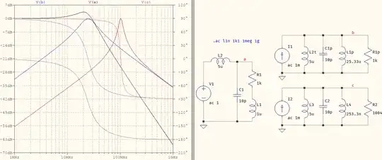
It can't be done that way unless you want it to be calculated at a fixed frequency, only. Otherwise, if you look at the first circuit, L2 and C1 form a lowpass (with a series RL as a load), while the second circuit is the equivalent of an L||C (with a resistive load, damping), which is a bandpass. Series to parallel transformations, and vice-versa, rely on the reactance, thus defined at a single frequency.


In the comment below, @jonk is right: some explanation is needed for the opening phrase.

That quality factor you mention has only a meaning for the simple 2nd order circuit and, in your case, its expression signifies the damping (there is more than one meaning). That can be achieved in your 2nd picture: the two inductances can be merged, leaving the parallel RLC. But its expression, then, will be particular to that topology. An LC lowpass (the kind that you have in your 1st picture) will have its own, and even then it only has meaning as long as the transfer function is a 2nd order. But the 1st picture is more complex than that, becaue the load is not purely resistive -- it's a complex impedance in the form of \$R+jX_L\$. And that makes the transfer function of the 1st circuit to become:

$$H_1(s)=\dfrac{1}{L_2C_1}\dfrac{s+\dfrac{R_1}{L_1}}{s^3+\dfrac{R_1}{L_1}s^2+\dfrac{1}{(L_1||L_2)C_1}s+\dfrac{R_1}{L_1L_2C_1}} \tag{1}$$

The 2nd one is the banal 2nd order bandpass. Overall, this is a 3rd order transfer function, even if the \$s\$ in the numerator means there is a zero that will cancel one pole. But the denominator can now be factored as two polynomials: a 2nd order and a 1st order. To make things more difficult, the meaning of Q is ambiguous now. Which one would you consider: the Q of the LC lowpass, or the Q of the series RL load? In fact, what's stopping you from considering the RLC circuit formed by R1, L1, C1? That, too, will have its own quality factor. These two have different meanings: the 1st is related to the damping of the pole, while the 2nd relates to the efficiency, or the "purity" of the inductor, or capacitor (real LC elements never have a pure 20 dB/dec slope).

And the meanings do not stop here, as you've seen in @LvW's answer (you can also see the Wikipedia article), but it would probably diverge a bit from the goal. I will add, though, that the part where I said "...at a fixed frequency, only." referred to the series-parallel equations, where Q is defined as \$Q_s=X_s/R_s\$, or \$Q_p=R_p/X_p\$. But this is only valid for the simple impedances in the form of \$R+jX\$, and has nothing to do with a 2nd order system.

But the reason I skipped over these is because I wanted to show you that there's no need to complicate and simply evaluate, visually, what you have and what you want it to become: there are two schematics with two very different topologies. In fact, your final sentence:

My next step is to simulate both circuits to see if the frequency response for the voltage across C1 is the same...

would have been more than enough to make you realize, for yourself, why the goal is not possible. Even if it would not have been clear enough from a visual inspection of the circuit, a simulation would have immediately revealed why that transformation is not possible. I suppose one of the hidden messages is to not be afraid of the simulators, they can often bring that "...oh!" moment.


I'd like to clarify one thing. The quality factor, Q, has a universal meaning: it represents the amount of damping of the poles or zeroes. This definition is universal and can be used anywhere, even for 1st order systems (e.g. a simple series RL). But because this is such a generic point of view, people attributed other meanings to it, to cater to the various other use-cases. For example, a lowpass is better defines in terms of damping, \$\zeta\$, rather than the quality factor, because it provides a more intuitive description in the impulse or step response; a bandpass is better represented in terms of its center frequency, \$f_0\$, in relation to the bandwidth, \$\omega_{BW}\$ where time domain analysis is needed then it's also more descriptive to say that the higher the Q, the longer the settling time. All these make use of peculiarities of the application in order to provide a more intuitive description of the system or its response. How would all these sound if, for all the cases, there would be one explanation, only: the damping of the poles/zeroes. It would only hamper the understanding.

So, while the Q that you're talking about does, indeed, make sense only at one frequency, it doesn't mean that it's only the resonant frequency, or other, fixed frequency. It can be applied just about anywhere else, but a sensible choice would be where numerical analysis would give meaningful numbers (e.g. if \$f_0\$ = 1 MHz and Q is calculated at 1 Hz). And if that Q is used as the basis for series-parallel conversions, then that can only be done at one frequency, only, not necessarily at \$f_0\$.

Here is something to think about: use the same 2nd topology but calculate the parallel RL for a different frequency. This is one possible result, where the two circuits on the right have calculated values at 1 MHz and at 10 MHz:

test

a concerned citizen
  • 21,167
  • 1
  • 20
  • 40
  • 1
    I might have been more dogmatic, saying that the OP would first need to define a meaning for \$Q\$. It doesn't have a single usage, from my experience. And the different usages are not all the same. For example, it may compare the initial energy vs energy consumed in a single radian. That, I suppose, could have meaning as you suggest -- for a fixed frequency. Another, though compares the center frequency to some meaning of bandwidth. That wouldn't make sense in the OP's case. Either way, your answer is sufficient which is why the +1. Or have I missed something? – jonk Jan 05 '22 at 10:21
  • @jonk You're right, I did skim over that, so I tried to add some sort of explanation, hopefully with the correct words. Jrive, I've updated the answer, maye it brings a few more meanings. – a concerned citizen Jan 05 '22 at 14:47
  • Please see my edited question. I added the results of my simulation --which now makes me re-read what you guys both wrote above in the context of my simulation which shows equivalency between the two circuits and Q as the ratio or peak amplitude to 3-dB bandwidth..... – jrive Jan 05 '22 at 15:24
  • I'm still digesting this answer -- I can't say I completely follow what it is saying. Isn't Q meaningful at resonance, and thus narrows the problem to a single frequency (or narrow band around the resonant frequency)? I recognize the two circuits are different, but the Q of the break frequency in the low pass, and the Q of the bandpass is the same --when isn't it? Like I said, still digesting the answer --i'm not doubting it, just working to understand the subtleties....And thank you both for engaging in the discussion --very educational. – jrive Jan 05 '22 at 15:56
  • @jonk, you wrote above, "That wouldn't make sense in the OP's case". referring to Q defined as "mpares the center frequency to some meaning of bandwidth" ---but that is exactly what I'm talking about....Why did you say that that wouldn't make sense in the OPs case? I'm missing something.... – jrive Jan 05 '22 at 16:03
  • @jrive Given your comments I realize this answer could prolonge to the size of a book. You had to adjust the magnitude of the `AC` stimulus to a very small value, `1.7m` (likely "hammered"). That, alone, should give you an idea that the two circuits are not the same. But if you're only interested in the region *around* the resonant frequency, then you could say the two are *very similar*, but not the same -- that only happens at precisely one frequency, the one you used for calculations. If you simulate from 47 to 47.12 MHz with 1001 points, you'll see what I mean. – a concerned citizen Jan 05 '22 at 17:19
  • Also try simulating from 1 MHz to 1 GHz, to see the larger picture. You'll clearly see that one response is of a lowpass type, while the other a bandpass. And if you'll adjust the values of the resistor to be higher, in the range of hundreds, or more, you'll see that as long as the quality factor is tamed, so do the differences between responses increase. It's a bit unfortunate that you chose those values because of the large Q. I'll add one last bit about Q in the answer in a bit. – a concerned citizen Jan 05 '22 at 17:23
  • @aconcerned citizen, no , that is the source transformation at the resonant frequency, ie, 1/(2*pi*47.1MHZe*2e-6) for converting the voltage source with series impedance to a current source with a parallel load. I am interested in the Q -- at resonance. Not the performance of the overall circuit. Did I just get luck and it happened to be the same in this case? – jrive Jan 05 '22 at 22:13
  • I just read your answer- very nice.- thank you. However, I don't think it is a fair comparison. The low pass filter has a pole where the 3dB break frequency is. It is this frequency where the Q would be of interest, and the frequency that you (or I, rather) would use to create the "equivalent" circuit (as far as Q is concerned). I believe the Q of your low pass is the same as the Q of your bandpass designed via impedance transformations at the 3dB frequency (node b in your sim). – jrive Jan 05 '22 at 22:30
  • @jrive In your case the series RL forms a zero that is close to the real pole (compared to the complex one). Given your numbers, I don't think it's random (the 9.7 and 2.67u values). And for the 2nd order transfer function, Q is a fixed value, irrespective of frequency; for RL or RC, it's established at a specific frequency. This is why you see different traces in my last picture, because, even if I kept Q the same, the reactance varies with the frequency, which influences the resulting parallel combination which, in turn, alters the resonance for the parallel RLC. – a concerned citizen Jan 05 '22 at 22:56
  • I don't follow...gonna have to re-read more carefully. But, I'll clarify what I'm saying (or trying to say, ;-) Starting from the low pass filter, it has a resonance that occurs at L2 in parallel with C1 and (L1+R1). If I do the impedance transformations at that frequency, I believe the resulting parallel RLC circuit's `Q` is identical to that of the 3rd order low pass filter considered throughout this discussion. Perhaps this is not correct, but your simulation and mine seem to support this assertion. – jrive Jan 05 '22 at 23:18
  • Let us [continue this discussion in chat](https://chat.stackexchange.com/rooms/132931/discussion-between-a-concerned-citizen-and-jrive). – a concerned citizen Jan 06 '22 at 09:39
  • 1
    @jrive Take the case of a 1st order low-pass filter: \$K\cdot\frac{1}{s+\omega_{_0}^2}\$. What is \$Q\$ here? There's the voltage gain \$K\$. There's the corner frequency \$\omega_{_0}\$. But there's nothing else there to see. Now suppose \$K=1\$ and \$\omega_{_0}=1\$ for convenience. (There's not particular reason we can't study that exact case, is there?) Now we have \$\frac{1}{s+1}\$. Tell me where a meaning for \$Q\$ lays in here? I'm not saying you cannot do it. But I'd like to see your definition, just the same. – jonk Jan 08 '22 at 06:52
  • 1
    @jrive For example, would you choose to square the characteristic in this case to find that \$Q=\frac12\$? If so, how would you choose to handle higher order, \$N=3\$rd and above? Would it be to use \$\sqrt[N]{\text{characteristic}^2}\$ in order to approximate a 2nd order equivalent and find \$Q\$? – jonk Jan 08 '22 at 07:10
  • @jrive I've added some replies in the chat (I'll delete this afterwards). – a concerned citizen Jan 08 '22 at 11:14
  • @jonk, there is no resonance in a first order system, so there is no Q. – jrive Jan 10 '22 at 05:15
  • @jrive I'd hoped you might follow why I wrote that last tongue-in-cheek comment, after everything else here. But I fear perhaps not. Time for me to leave this discussion to my betters. – jonk Jan 10 '22 at 05:54
  • @jonk --thank you for the discussion. Have a look at this paper: http://www.arrl.org/files/file/QEX_Next_Issue/2015/Sep-Oct_2015/Kaune.pdf....and yes, I apologize, I didn't get it. – jrive Jan 10 '22 at 20:26
  • @jrive I don't have that much time now, so I'll read that later on, but the introduction seems to be a red flag because of two things: the author has only recently started reading about the Pi networks, and the "Q" found by him "*fairly accurately predicts the bandwidth*". This last part doesn't sound good, at all. For any 2nd order, Q *accurately* predicts the bandwidth. I've also given a small example in the chat, did you see it? By your logic, a 4th order Butterworth and a 4th Chebyshev filter are the same if they have the same f0 and BW. – a concerned citizen Jan 10 '22 at 21:43
  • @aconcernedcitizen, you misunderstand my logic --I never said anything remotely resembling "a 4th order BW and a 4th Cheb filter are the same --- but, they are, except for the flatness and ripple of the passband!!....set your biases aside and read the article-- be receptive to the possibility that you might be incorrect or missing the point. The more I know , the more I realize I don't know....humility is a good thing. – jrive Jan 11 '22 at 18:28
  • @jrive Your whole point of view is that a transfer function with an order greater than 2 has a "quality factor". By that logic, my example would be true, which is not. Sadly, at this point I see that your purpose is to simply debate this point of view which, if you'll forgive me, I won't; the discussion is already much too long for the message it should contain. This is a Q&A site, not a forum. If my answer does not address the problem in your OP, feel free to use the voting system appropriately. – a concerned citizen Jan 11 '22 at 20:45
  • @a concerned citizen --ok, yes. I thank you for the discussion. – jrive Jan 13 '22 at 05:27