1

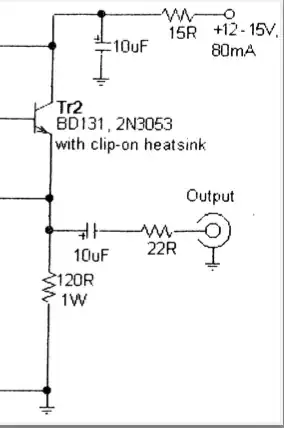
This circuit has a 15 ohm resistor in series with the 12-15v power supply line, just before the 10uF decoupling capacitor. (It is from an RF preamp design in "LF Today," a book for radio amateurs using frequencies below 1 MHz.)

Power Supply Input Series Resistor

I believe the resistor's purpose is to protect the power supply against an initial surge of current charging the capacitor. Is this correct?

This resistor would limit the maximum draw from the power supply to 1A under any circumstances, at the cost of dropping the supply voltage by about 1.2v in this case (assuming the 80mA value shown on the schematic).

I want to know how important it is to include this series resistor as practical matter. 10uF is not a huge value, and in fact I learned here USB powered device with multiple Decoupling Capacitors that 5v USB power supplies are expected to tolerate that much in connected devices.

If I was connecting this to a big 12v lead-acid battery, I think it would be justified in leaving it out altogether. But if I were to use an inexpensive 12v "wall wart" supply, what is the likelihood that the supply would be damaged by the inrush current to the 10uF capactitor?

Is this series resistor overkill, or is it generally accepted good design to always include a series resistor when using a decoupling capacitor in such circuits?
Michael
  • 23
  • 3
  • 1
    15R is both an RC noise filter and passive current limiting and Pd rating must be large enuf with 50% derating to not get to 125'C. Adding a PNP with 0.7V drop max would be better for desired active current limit – Tony Stewart EE75 Jan 04 '22 at 15:54
  • If only 80mA I^2R= ~ 100 mW at 1.2V drop. But more if Shorted. Its a reasonable protection design. 80mA*150R= Vdc.out=1.2Vdc @ 1W is OK b ut 2W is cooler. If shorted everything still gets very hot, but might not fail immediately. Load should be >> 100 ohms pref. High R, but input bias of 1.2+0.7 is not shown – Tony Stewart EE75 Jan 04 '22 at 16:03

1 Answers1

1

The series resistor is not there to limit the turn-on current spike (although it certainly does this too). A 10µF capacitor is almost negligible when it comes to turn-on currents as you have already realized; in fact, its own ESR will limit the current spike as well. It certainly won't damage anything even without the resistor. The 15 Ohm resistor is instead inserted there to form a RC low-pass together with the decoupling capacitor. It has a cutoff frequency of almost exactly 1kHz, which is right within the range needed to attenuate high-frequency ripple that's produced by switchmode power supplies such as your 12V wall wart. You shouldn't omit the resistor, otherwise the circuit's performance may be degraded.

Things are different if the 10µF capacitor is a tantalum type, though: These need a series resistance to stop them from blowing up. (Current spikes cause tantalum-MnO2 capacitors to short out.) It'll still act as a low-pass as well, of course.

Jonathan S.
  • 14,865
  • 28
  • 50