Antonio51,
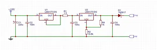
Try this one:
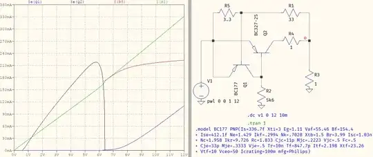
For the spice test try this one:
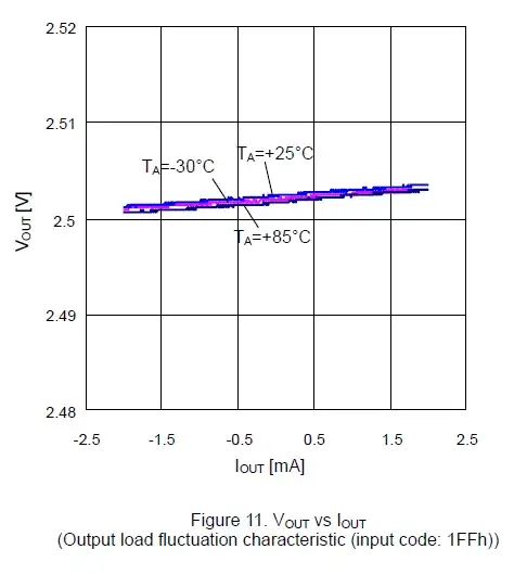
You should get a plot like this:
Please let me know if there are still any more questions.
PS: the circuit is a circuit breaker (like an electronic fuse) and not a constant current limit circuit.
Here are the result of my tests I posted in the original post:
Circuit driving 400mA:
LED shows that Q1 is ON:
When circuit is off, it only draws 50mA which is the current in the Q2 collector and RB:

Looking at my old electronic courses, I came up with the circuit below from my "neets-navy-electricity-eletronic-training-series", "Mod09 - Wave-Generation and Wave-Shapping Circuits", "Figure 3-11". Weird circuit don't you think? PS: I edit it for you folks to understand it better.

The circuit in "Figure 3-11" of the navy electronic training series presented above is a monostable multivibrator, where one of the transistors is saturated while the other is cut off.
Because the circuit is not symmetrical, when power is applied Q2 will saturate first, cutting Q1 off in the process. This is the stable state. When Q1 is off, its collector is at ground (no current flowing through R1). Q2 is saturated and its collector to emitter voltage (VCE) is very low and its collector is practically at +Vcc (in reality +VCC minus the drop of VCE), making the base of Q1 (through R3) also practically at +VCC, holding Q1 off.
If a positive (pulsed or not) voltage is applied to the base of Q2, it will cut Q2 off, lowering its collector from almost +VCC towards ground. In the process, the base of Q1 will become more negative, through R3, and Q1 will start to conduct, quickly saturating. The collector of Q1 will rapidly rise to almost +VCC. This sharp voltage increase is coupled through C1 to the base of Q2 causing it to cut off even further. This is the unstable state.
Once the positive voltage ceases to exist (if pulsed) or is removed (if not pulsed) Q2 starts to conduct through the network of R2 and C1, returning the circuit to its stable state in a time determined by the product of R2 and C1. Increasing/decreasing R2 or C1 will increase/decrease the time that the circuit stays in the unstable state.
It is important to note that a capacitor Capacitance is determined by the formula below, where K is the dielectric constant, A is the area (in square inches) of one of the capacitor plates and d (in inches) is the distance between the plates:
The interesting thing about the above formula is that if you decrease the distance between the plates the capacitance increases proportionally. If you decrease this distance towards the limit of zero, the capacitance will increase towards the limit of infinite, and the time constant will be infinite, resulting that the unstable state will stay until Q1 is cut off, or the power supply is removed and reconnected.
This is what is happening with the first circuit presented in this answer (the one with the Rsense resistor). The circuit is a modified monostable multivibrator, where the C1 capacitor have been shorted (theoretically making its capacitance infinite), RB is the equivalent resistor of R1 and R2 in parallel, R3 is resistor RT and R4 is the load resistance. Note: Q1 and Q2 are exchanged between the circuits (Q1 is Q2 and Q2 is Q1 in the second circuit diagram).
In summary, there are three types of current limit circuits that I know so far:
- Constant current limit circuit;
- Fold back current limit circuit; and
- Circuit breaker current limit. Or current limit circuit/breaker as the youtube video that presented this configuration is called. This is the first circuit in this answer and works with or without Rsense (Rsense makes the circuit more accurate and independent of the different parameters that two transistors of the same type may have. It also makes the circuit independent of the power supply, as with different power supplies you will have different currents flowing on the same resistor value RB.)
As I have mentioned in this answer, and in the original post (also the youtube video describes it better) the transistors need to be running saturated for the circuit to work and resistor RB needs to have a base current such that will keep its transistor saturated for the current the circuit is trying to limit.
For a load current of 500mA, and the BC327, the base current of RB needs to be at least as high as 50mA, as in saturation mode the transistor will be having a gain of as little as 10 (in saturation mode a transistor behaves almost as a fixed resistor and its beta gain have minimum effect as compared when the transistor is not in saturation mode.)
Resistor RT needs to be such that will keep the transistor saturated when it is conducting through RB (50mA for the load current of 500mA).
One more thing. When the transistor is saturated and the circuit on, it is the current flowing in the load that determines the current of the circuit and consequently the VCE voltage drop. Once that current is high enough to make VCE (+ Rsense if it is used) above 0.7 volts, the circuit will switch from “stable” to “unstable” state like in the “equivalent” multivibrator circuit.
EDIT: It is interesting that no one noticed my crazy statement that a short circuited capacitor would have an infinite capacitance. So, to avoid confusion, I am reviewing what happens with the circuit once it is in its initial stable state:
Q2 is saturated and Q1 is cut off, with C1 capacitor charged as in the diagram below:
If a positive (pulsed or not) voltage is applied to the base of Q2, it will cut Q2 off, lowering its collector from almost +VCC towards ground. In the process, the base of Q1 will become more negative, through R3, and Q1 will start to conduct, quickly saturating. The collector of Q1 will rapidly rise to almost +VCC. This sharp voltage increase is coupled through C1 to the base of Q2 causing it to cut off even further. This is the unstable state.
Once the positive voltage ceases to exist (if pulsed) or is removed (if not pulsed) C1 starts to discharge through the network of C1, R2, and Q1, turning Q2 ON in the process, returning the circuit to its stable state in a time determined by the product of R2 and C1. Increasing/decreasing R2 or C1 will increase/decrease the time that the circuit stays in the unstable state.
But what if the capacitor was not there? The +VCC of Q1 collector would stay there indefinitely, keeping Q1 ON and Q2 OFF.
If instead of a positive voltage applied to the base of Q2, it was the collector-emitter voltage (VCE) of Q2 to increase above a certain value (VCE > 0.7V), because the load current through R4 increased, the base of Q1 voltage would decrease, through R3, turning Q1 ON.
This is what is happening with the first circuit presented in this answer (the one with the Rsense resistor). The circuit is a modified monostable multivibrator, where the C1 capacitor have been replaced by a jumper, RB is the equivalent resistor of R1 and R2 in parallel, R3 is resistor RT and R4 is the load resistance. Note: Q1 and Q2 are exchanged between the circuits (Q1 is Q2 and Q2 is Q1 in the second circuit diagram).


