I want to maintain a constant frequency of 50MHz for my Nexys A7 FPGA Board. Currently, the internal clock is 100MHz. How can I implement a digital clock manager in VHDL/Verilog to make sure my frequency is reduced to 50MHz and maintains the same throughout?
-
For what exactly do you need 50 MHz ? FPGA have a lot of internal clock generator ressources and it is common to run different stuff at different clocks. So can you derive a 50 MHz clock and use it for all your blocks ? – tobalt Jan 03 '22 at 05:20
-
If rising_edge(clk) then clk2<= not clk2; end if; – TQQQ Jan 03 '22 at 05:23
-
2@TQQQ That's a bad method. See the answer below which correctly describes the problems (skew, fanout) with routing/generating clocks in logic. – TypeIA Jan 03 '22 at 06:11
-
still could work. judging by the question it's quite possible that nothing better is required. you don't always have to be more saint than the pope – TQQQ Jan 03 '22 at 08:01
-
2@TQQQ 50 MHz; No, such a clock will fail miserably on FPGA on-board testing, unless the clocked design is a small design like simple counter or so. – Mitu Raj Jan 03 '22 at 08:33
-
so there is a case when it could work? come on, don't tell me you never did it – TQQQ Jan 03 '22 at 08:40
-
@MituRaj just to be clear, obviously this is not the optimal way to clock the internal logic. however, in my experience 100MHz is a comfortable frequency for anything inside, if written correctly. So 50MHz is most probably for something outside the chip- meaning it can probably suffer a bit of a jitter. I don't know for sure. But it's clear to me that such a tool needs to be in anyone's toolbox. – TQQQ Jan 03 '22 at 08:47
-
1It's not just about skew or jitter, it is also about rise time. For eg: logic clocked by clock dividers fail for frequencies > 25 MHz on an Artix-7 due to poor signal integrity, when the design is "complex" enough with high fanout. – Mitu Raj Jan 03 '22 at 09:01
-
1@TQQQ Please be polite and respectful. I found your comment offensive. While there _are_ simple cases where your suggestion _could_ work, this forum is about providing sound advice. What you propose is objectively bad practice, and there is a better way, as answered below. – TypeIA Jan 03 '22 at 09:55
-
I guess it's very respectful of you to state certain objective truth. Well, go ahead, get offended. In real life what i suggest not just could work, it worked i many instances absolutely objectively. – TQQQ Jan 03 '22 at 23:41
-
@Mitu Raj this 50Mhz could drive stuff outside the fpga. Just as another example, SPI clocks normally driven similarly without any problem. – TQQQ Jan 03 '22 at 23:43
-
I didn't say NO. All my comments, I was talking in the context of the logic clocked INSIDE FPGA, which the OP is interested in. – Mitu Raj Jan 04 '22 at 03:47
-
Not that we are on trial or anything. But in his first sentence he is talking about "BOARD". I read it as a clock for outside fpga. – TQQQ Jan 04 '22 at 05:35
2 Answers
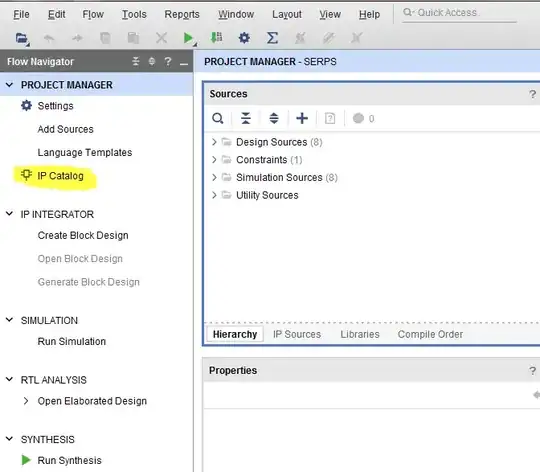
You cannot do so from native VHDL/Verilog because clock signals cannot be properly routed through the logic fabric. Too much skew. They need to go through the dedicated clock routing networks that span the entire FPGA. That means you need to use Clocking Wizard in the IP Catalog in Vivado to configure the hardware PLL or DLL.
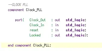
After you finish the Clocking Wizard, it generates a component.
It also provides template code for you to instantiate the component which gives you access to the signals. I can't remember how you bring up the template code at the moment. I think it's a right click option in a menu somewhere. Or maybe my memory was off and WebISE provided template code but Vivado does not. In any case, you don't really need a template because the Clock Manager is simple and you named all the signals in it so you know what signals are present to write your own component declaration and instantiation.
- 54,733
- 4
- 67
- 153
-
1In addition to the skew issue, there's also fanout. The dedicated clock fabric is designed for high fanout, unlike regular logic. Also combinational logic (if present) can introduce glitches. There are many reasons to do it as you have described and never in logic. – TypeIA Jan 03 '22 at 06:12
-
Yes, I now understand why it is always safe to follow the method that is mentioned above. Just for the sake of understanding I tried to develop a VHDL code for DCM which resulted in a lot of disturbances at the output end. Regards, Divya – div_01 Jan 04 '22 at 05:40
There is an Digital Clock Manager (DCM) IP provided by the manufacturer to generate the clock of desired frequency. You can use 100MHz as input and can manually select 50MHz as output. Or else, you can also generate it by yourself by capturing every other clock rising edge in the code itself.
- 347
- 2
- 9
