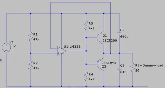
EDIT: I built up the circuit shown below. I had the power transistors lying around, as they're a type used for class B audio amps, and they're dirt cheap on the "jungle river" website--about 12 bucks for five pairs. Without heatsinks (which clearly will be the thing I add next!) it runs well with up to 31 V input (the highest that my single rail PSU will drive) and with the 50 ohm "single sided" load. It's pushing about 300 mA through Q1 at this point, and while the transistor gets hot, I doubt I'll ever get that big of an imbalance. If I do, well, I expect I'll have the heatsinks in place by that point.
Initially, I had the typical diodes between the transistors' bases and the op-amp's output, but this created (as it should!) a significant quiescent current, particularly at higher input voltages. I realized that I doubt I'll ever need to get rid of the "crossover distortion", in particular because of the smoothing caps on the output. Better in this case to reduce the quiescent dissipation.

I have a feeling that the hfe of these transistors will likely be insufficient to get really huge "ground" currents. I toyed with configuring them in something like a darlington pair with a smaller transistor to drive them, but I think this will be fine for my needs right now.
So, many thanks to those who helped out with reassurance, despite the "poor engineering choice" involved here. It worked out dirt cheap, probably under $5 for everything, though it's hard to say, since I had all this on hand, I'm confident it's more than capable enough for what I need it for (usually driving op-amps!) and it was a great learning experience. Not least I learned that when you reverse-voltage an electrolytic, it a) draws quite a lot of current, and b) really will explode if you don't notice that the case is expanding and get it out of there first!
I recently took delivery of what I thought was a dual rail bench power supply, but turned out to be only single rail.
I only occasionally need a dual rail, and then not with a great deal of power. I've seen myriad options for creating a split rail from a single one, from a pair of resistors to a full-fledged switch mode / inverter type approach.
A common idea that I found was to use an op-amp to track the center voltage. Pros/cons for this are generally documented as being fairly simple (compared to switch mode approaches, which are too complex for my interests) while providing far better tracking than simple resistors (which would be hopelessly fiddly and imprecise for me), but with the limitation that only a few milliamps of "ground" current can be handled.
I'm thinking that if I took this as a starting point, but added what would look like the output stage of a class B audio amplifier, with modest power transistors, I might reasonably beef this up to a useable level (I doubt I'll ever need more than 250 mA when working in this mode, and commonly much less).
I can see that I'll have to be careful with the crossover point (just as I would in building an actual class B amp :) but are there any other considerations? Has this been done before? Is it a blatantly foolish idea that misses some fundamental problem? If it's workable, is there a well known reason that it's not one of the commonly discussed options? (perhaps most people, unlike me, are perfectly happy playing with switched mode circuits--I'm not, as my two previous attempts were entirely unsuccessful for reasons I've never been able to fathom, by contrast, class B amps have worked for me, albeit about 40 years ago!)