5

I'd like to make a DIY kinetic energy harvester and wish to use the electromagnetic method to generate electricity. So far I know the following materials that I'm going to use:

  1. NdFeB magnet
  2. Induction coil made up of copper wire
  3. Dry cell (for electricity storage)

And I wonder should I add a rectifier into the circuit before the dry cell is charged?

PeterJ
  • 17,131
  • 37
  • 56
  • 91
Rex
  • 61
  • 1
  • 2
  • Rex - see addition to my answer. For very small caps (100 pF - 10 NF) the meter will discharge them in time. – Russell McMahon May 20 '13 at 17:46
  • See [this article](http://web.eecs.umich.edu/~prabal/teaching/eecs598-w10/readings/VSD+09.pdf) for valuable insights into the several options available for such energy harvesting. – Anindo Ghosh May 21 '13 at 16:10

1 Answers1

5

If your circuit is mainly as described with no electronics in the middle then you definitely need a diode. What you then have is effectively an alternator with diode rectification. Voltage generated needs to be greater than battery voltage + a diode drop.

If your system applies a magnetic pulse to the coil and then removes the field rapidly you may be able to get an inductive "kick" of much greater voltage than was generated by the magnet directly.

If your generated voltage is less or much less than the battery voltage then you will need a circuit to step this up to battery voltage. There are a range of "energy harvesting" ICs available from various manufacturers that perform this function.

LT overview very nice introduction to their products in a range of energy harvesting areas.

LT DN491
Discusses LTC3105. Shows use of 2 cell = 1 V PV panel BUT this would work with inductive input.

LT DN428
Demonstrates LTC3526 boost converter.
They are using it from a single cell but again would work with inductive input.

LT Journal uses LTC3108 & LTC3109 at very low Vin. RTEG in this case, but ... .

LTC3588 piezo in

Magazine article useful.

SOLAR relevant but not directly applicable

MAX17710 Energy-Harvesting Charger and Protector

TI BQ25504

Datasheet potentially useful

Ideas galore


ADDED:

@Rex - did you look at the app notes. Some make it easy enough.

BUT if you substitute a capacitor for the battery you can get a good idea of what is happening. A common DMM (digital multimeter) a coil, a diode and a magnet and a say 10 megohm resistor across the capacitor when wanted, should be about enough.

schematic

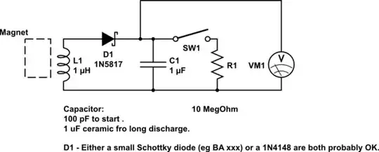
simulate this circuit – Schematic created using CircuitLab

A small capacitor (100 pF to say 10 nF range) should charge with ease. As cap gets bigger charging may take multiple magnet swipes. Placing the resistor across the cap will discharge it in time. 10M and 1uF ceramic or Tantalum cap will discharge to ABOUT 60% in 10 seconds. Smaller caps faster.

Russell McMahon
  • 147,325
  • 18
  • 210
  • 386
  • If i didnt direct the circuit to a dry cell instead i direct it to measurement appratus,is it possible to generate some output data and display on the appratus?And im kinda don't know what kind of instrument needed to measure the output current and voltage,would you like to recommend me some,please?It is damn difficult for me the mechanical engineering student to understand the electrical stuff..Thanks a million 1st – Rex May 20 '13 at 13:23
  • @Rex did you look at the app notes. Some make it easy enough. BUT if you substitute a capacitor for the battery you ca get a good idea of what is happening. A common DMM (digital multimeter) a coil, a diode and a magnet and a say 10 megohm resistor across the capacitor when wanted, should be about enough, A small capacitor (100 pF t say 10 NF range) should charge with ease. As cap gets bigger charging may take multiple magnet swipes. Placing the resistor across the cap will discharge it in time. 10M and 1uF ceramic or Tantalum cap will discharge to ABOUT 60% in 10 seconds. Smaller caps faster. – Russell McMahon May 20 '13 at 17:38
  • @RussellMcMahon - so if one built the circuit above eliminating the meter and replacing R1 with a resistor and an LED (and a beefier capacitor), could one make a shake light? – mikeY May 21 '13 at 15:20
  • @mikeY - Essentially yes. Using a full wave bridge of Schottky diodes would probably be superior to get bidirectional action. – Russell McMahon May 22 '13 at 02:40