7

Suppose, I have a long trace (e.g. 30 cm) that is driven from one end and that is carrying a DC or LF voltage (e.g. audio signal or power trace). The other end of the trace is high impedance compared to the trace's characteristic impedance: Either a high impedance device input, or it could be also a high impedance only at high frequency (e.g. series ferrite chip bead).

schematic

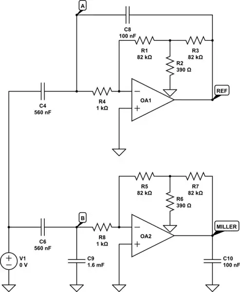
simulate this circuit – Schematic created using CircuitLab

Such traces can ring at the "open" end when that end receives interference e.g. from switching power supplies. The antenna effect can then cause EMI issues. Sometimes it's possible to relocate things, sometimes not. One remedy I have used is to bond the "open" end to GND using a capacitor of e.g. 100 pF. Or even with multiple caps along the length for long lines to also quench harmonics.

Now I have read somewhere on EESE (can't find the link right now) that this is a bad practice and a series resistor should be used with the capacitor. But doesn't a series resistor with the capacitor actually make the capacitor somewhat useless?

I can't really simulate this well with Spice and I don't have any field solvers, so I hope that people here may have some idea how to quench ringing in such lines properly?

winny
  • 13,064
  • 6
  • 46
  • 63
tobalt
  • 18,646
  • 16
  • 73
  • 1
    I doubt very much that a 30 cm trace will naturally produce any ringing at the far end when the driven end frequency is audio. You might have some other thing that causes it so, look for root-cause. It's possible that you might see the ringing at the driven end and, that might be caused by the driver and the capacitive load of the trace. – Andy aka Dec 13 '21 at 09:39
  • Yes, @Andyaka you are completely right. It was probably not clear in the question text (I will edit it) The offending EMI often comes from SMPS for instance. – tobalt Dec 13 '21 at 09:41

2 Answers2

19

Connecting a capacitor to ground at the end of a line changes the far end from open circuit to short circuit at RF.

This will change how the line resonates, not stop it from resonating. If it's driven from a low impedance, then what were odd λ/4 resonances will become even multiples of λ/4, and vice versa if it's driven from a high impedance. This will shift the frequencies, and positions of anti-nodes, so may cure any existing problem that the line is causing. It may also cause new problems to happen that were there not before.

Putting a resistor in series with the capacitor, equal to the impedance of the line, terminates the line so stops it from resonating. This stops any magnification of possible EMI signals. An alternative is to place a series resistor at the driving end of the line.

Very difficult EMI problems might see you putting a resistor at each end, or segmenting the line into shorter, preferably unequal length, sections with ferrite beads.

Transmission lines, resistors and capacitors can be simulated very well in SPICE. I'm not sure whether there are any good models for ferrite beads available, perhaps somebody could link to some in comments if there are.

I had a specific problem in a synthesiser which was not EMI as such, but a power line between two otherwise isolated sections. For 'best' (as I thought) power trace filtering, I used a ferrite bead in series with the line which had a 1k maximum resistance. This was so close to an open circuit that, together with a shunt C at the other end, I got an odd λ/4 resonance which helped a 1GHz signal crawl from one area to the other along the power line. Changing the ferrite bead to one with 100Ω max resistance terminated the line, eliminated the magnification of the resonance, and restored the isolation I needed.

Neil_UK
  • 158,152
  • 3
  • 173
  • 387
  • Thanks for the explanations. Makes sense with the right context :) I have never really liked transmission lines in LTspice (don't know about other softwares) for their obvious flaw of having no DC/LF transmission. So i usually use lumped LCs which would complicate such a sim. – tobalt Dec 13 '21 at 09:39
7

I hope that people here may have some idea how to quench ringing in such lines properly?

Maybe you should consider what the best practices are used for routing an audio signal from A to B. Best practice is to use balanced signalling methods. So consider this unbalanced signalling scenario first: -

enter image description here

The image is taken from my answer here and, for thinking about a PCB with a ground plane, just regard the the local ground extending back to the sensor (aka audio device) via a PCB ground plane. Do you see the issue that this circuit has with noise and interference?

If you used a balanced approach you would get superior results: -

enter image description here

So, ignore the cable and think of it as two closely linked PCB tracks. And, if your audio source is "single-ended" you can do this (works for data and audio signalling): -

enter image description here

Again, the cable should be regarded as two closely linked PCB tracks. They key to all of the above is: -

So, this can be regarded as "prevention is better than cure" i.e. give the vulnerable audio signal the best chances for success. But, you may need to take this further by suppressing induced (or capacitively coupled) noise voltages. These include: -

  • Burying the balanced audio PCB tracks into an inner layer with a ground plane above and below
  • High-frequency dissipative shunt between the two balanced lines so that high-speed transient noise can be reduced (thus making the audio receiver have less of a hard job fighting against them despite them being common-mode).
  • High-frequency dissipative shunts to ground plane from each line (needs care and component accuracy).

A dissipative shunt (as mentioned above) is basically a snubber i.e. a capacitor that passes the HF in series with a resistor that dissipates the energy.

Andy aka
  • 434,556
  • 28
  • 351
  • 777
  • Re your second picture for a single-ended source, this may not work so well. The single-ended driver has an output impedance which adds to Rs on the signal path and affects that balance. If you make Rs large then the difference becomes negligible, but then you have the problem of high output impedance which attenuates the signal going into the receiver. If you replace the direct connection to 0V with a second single-ended driver with its input at 0V solves the problem. – Graham Dec 14 '21 at 08:56
  • @Graham just use your imagination a little. I called it Rs because it stands for source resistance and, that can mean the internal driver source resistance or, it can mean the internal driver source resistance plus whatever extra resistance you want to put in series external to the driver. I think you refer to my 3rd picture maybe? – Andy aka Dec 14 '21 at 09:01
  • Oops, yes - didn't scroll back up far enough. :) Fair point if you can do something equivalent to the driver output impedance, yes. – Graham Dec 14 '21 at 09:44
  • It's just all lumped together to make it clearer (or not)! – Andy aka Dec 14 '21 at 09:57