6

The 555 astable oscillator seems to be usually implemented with one common resistor between the charging and discharging paths of the capacitor.

555 astable, DISCHARGE between two resistors

Is there something wrong with putting one resistor for the charging path, and one for the discharging path?

555 astable, one resistor on the discharge line, one going to Vcc

Strayed101
  • 75
  • 4
  • 2
    Go build it, attach an oscillsocope, see the result and have a look whether you can explain the result. Oscilloscope are like debuggers. They rarely lie to you. – Thomas Weller Dec 13 '21 at 17:10
  • @ThomasWeller Thank you for your comment, I take note of the advice. I can say, however, that they don't lie to you at all when you don't have any. It seems, indeed, that to put this into practice, one may need an oscilloscope. Or a 555. – Strayed101 Dec 14 '21 at 08:14

2 Answers2

10

Is there something wrong with putting one resistor for the charging path, and one for the discharging path?

There's nothing wrong with it other than at some point, the resistor in the discharge pin will never properly discharge the capacitor to a low enough value to cause a charge sequence to begin again. That added resistor is fighting against the pull-up resistor and the lowest voltage it can discharge the capacitor to is determined by both their values and the power rail voltage.

But, who is to say that on some circuits, this might not be desirable.

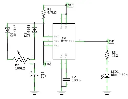
Maybe you are actually looking for something like this: -

enter image description here

Taken from this 55 tutorial.

Here's another variation originally from here: -

enter image description here

Andy aka
  • 434,556
  • 28
  • 351
  • 777
  • About the circuit with diodes: the tutorial doesn't seem to mention it, but shouldn't we replace Log(2) in the charge time formula with Log((2/3*Vcc-Uf)/(1/3*Vcc-Uf))? It actually accounts for a 45% difference when Vcc=5 V and Uf=0.7V. But then we also get a dependence with respect to Vcc which isn't necessarily so much fun... – Strayed101 Dec 14 '21 at 07:48
  • 1
    Sorry but I'm not familiar with the formula or how its derived. I'm aware of 555 timers but only because they've been around nearly as long as I have and, in my decades in EE I've seen a few circuit variations like the ones with diodes. But, I've never used one or bought one so, I can't comment on the formula. Maybe raise a new question and, fingers crossed, you might get an answer. – Andy aka Dec 14 '21 at 07:59
  • Thank you for your comment. The coefficient (which simplifies to Log(2) = 0,693 when Uf = 0) arises when expressing how long it takes for the capacitor to reach a certain voltage, having derived the voltage u(t) across the capacitor, in series with the resistor (and the diode), when the supply voltage shifts from a constant value to another. I'll be fine with that for now. – Strayed101 Dec 15 '21 at 08:23
4

The charge discharge cycle depends upon 1/3 and 2/3 of capacitor. This means that as long as discharge resistor is below 50% of charge resistor, the circuit will work. This is completely different than normal 555 behaviour, where high and low could be controlled.

Since discharge resistor is fighting against charging resistor low pulse width is harder to determine. This means you could get <50% duty cycle.

At least Falstad simulator looks like it will work.

enter image description here

Lelt discharge resistor was 7kΩ, middle 7.5kΩ and right 7kΩ.

enter image description here enter image description here

StainlessSteelRat
  • 7,851
  • 2
  • 18
  • 34