0

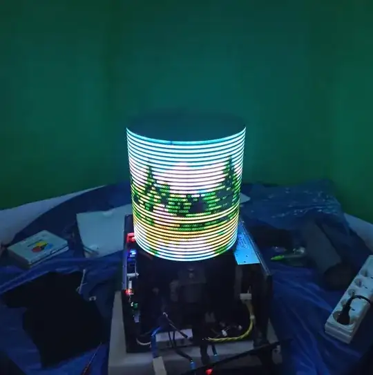
I built POV display with HD107S LED strip (similar to APA102), It uses Raspberry Pi 3 and ESC module to drive the motor. At first on the breadboard the POV works well, at this time the strip LED circuit and the ESC circuit were separate.

But now after I made one PCB that contain the LED strip circuit and ESC, some noise appear at some LEDs while the POV displaying. I found that the source of the noise is the motor, because when I shut it down the noise disappear. How can I eliminate this noise?

This is before assembling:

enter image description here

And this after assembling in one PCB: enter image description here

NOTE: the noise doesn't appear in this photo, because it comes and go, it happen for some LEDs. For example when it suppose to display juste green or blue it display red or other color randomly.

This the electronic schematic:enter image description here Top copper: enter image description here Bottom copper: enter image description here Traces that pass high current: enter image description here
winny
  • 13,064
  • 6
  • 46
  • 63
0ussama
  • 111
  • 1
  • 6
  • Seems like your pcb design is faulty. You would need to fix this. Since we have no idea of your schematic or pcb layout we cannot offer any solid solutions. – Kartman Dec 12 '21 at 06:38
  • @Kartman Now you have every thing . so can you tell me what is the problem and how to fix it ? – 0ussama Dec 12 '21 at 08:34
  • Everything? Draw lines where the heavy currents are flowing on your pcb. – Kartman Dec 12 '21 at 09:12
  • I just post image that shows traces that pass high current – 0ussama Dec 12 '21 at 09:22
  • 1
    There is no decoupling capacitor on IC2 and its unused inputs are floating. – bobflux Dec 12 '21 at 10:01
  • Where are your decoupling capacitors? Where is the motor connected? Does it have bypass capacitor and flyback diode? – winny Dec 12 '21 at 13:22
  • @bobflux Do mean that if I add decoupling capacitor and connect unused inputs to GND . This will solve the problem – 0ussama Dec 13 '21 at 15:24
  • It will solve one problem, but no-one can say if it will solve "the" problem... – bobflux Dec 13 '21 at 15:28
  • @winny C3_C4_C5 , Motor connected at X3, yes it has flyback diode and also bypass capacitor (if you mean 100 nF between motor terminal) – 0ussama Dec 13 '21 at 15:33
  • 1
    Do you use PWM on the motor or just on/off? – bobflux Dec 13 '21 at 15:55
  • I can't tell from the schematic. Where is decoupling for IC1, IC2 and IC3? How much does your 5 V drop to at the instant of motor turn-on? Again, I suspect insufficient decoupling. Also, please avoid slicing up your ground plane - no long traces there. – winny Dec 13 '21 at 16:11

0 Answers0