-1

I have a problem that waveform distorted after adding high ohm resistor, (second figure shows that resistor voltage which doesn't follow of input pulse (yellow).

So I added Darlington pair right after 500k resistor node to avoid distortion. But nothing has been changed in practical case.

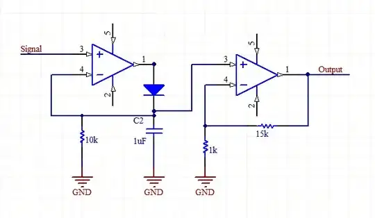
Real Circuit is more complicated but I put this image for more easy understandings.

Oscilloscope Result


Note: Circuit configure is for easy understanding, actual one is more complicated. Thanks
TonyM
  • 21,742
  • 4
  • 39
  • 62
  • 1
    You should post the circuit you're measuring, and how your scope is connected to it. Think: do you see the same distortion in a transient simulation of your simple circuit in LTspice? – TypeIA Dec 10 '21 at 06:38
  • No question, no schematic, not anything. – Andy aka Dec 10 '21 at 09:14

2 Answers2

5

The problem lies with capacitance in your oscilloscope and stray capacitance elsewhere. The resistor on its own cannot distort the signal. Try changing your oscilloscope probe from from 1X to 10X.

Math Keeps Me Busy
  • 18,947
  • 3
  • 19
  • 65
0

An oscilloscope with 10pF input capacitance, along with the 500k in your circuit, form an RC filter with a cut-off frequency of 35kHz which is enough to chop your 500kHz signal.

So I added Darlington Pair right after 500k resistornode to avoid distortion. But nothing has been changed in practical case.

If the intention is to buffer the signal then you should go for a circuit with very low input capacitance and very high input resistance. Another option is to use a buffer formed by a high BW (e.g. at least 10 MHz), low input bias current (e.g. in nA range) operational amplifier.

Rohat Kılıç
  • 26,954
  • 3
  • 25
  • 67