0

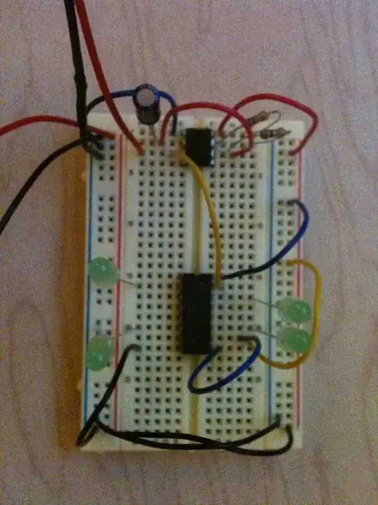
I've created the circuit below and have calculated the following values:

  • R' (equivalent resistance of entire circuit) = 1 / ((1/470) + (1/470) + (1/470)) = 157 ohms
  • I1 = VBattery / R1' = 6V / 157 ohms = 38.5 mA
  • I2 = 6V / 470 = 12.76 mA

This seems correct to me since, because all three branches have equal resistance, each gets a third of the current supplied and 12.76 * 3 is roughly equal to 38.5 because of rounding.

3 parallel branches

I've built this circuit using a breadboard to check my calculations and I1 and I2 don't match. I'm aware that physical components won't be exactly the same as what they say they are, but I'm way off.

For example, these are the values I've measured:

  • VBattery = 6.4V (this is fine, I understand it won't be exactly 6)
  • I1 = 28 mA
  • Each of the resistors are 476, 470 and 465, so this should give R' a total resistance of 155.8 ohms.

So the current I'm actually drawing is 28 mA instead of the 38.5 mA I've calculated.

The current on each branch is around 9.25 mA which at least makes sense since 9.25 * 3 = 27.75 which is very close to the supplied current that I'm measuring. But again, from my calculations using ohms law, the branches should be drawing around 12.76 mA.

Lastly, based off the current of 28 mA and the total resistance of 155.8, that implies the battery is only providing 4.36V, but I've measured and it's definitely providing 6.4V.

Update

I've rebuilt the circuit without the LEDs and the measurements I'm taking now match (or are very close to) the calculations I made.

But what I still don't understand is how the LEDs in the original circuit affect the calculations. People have correctly commented that I've just ignored them and that the voltage drop of 2V that they take is the 2V I was missing in my final point about 4.4V being less than the 6.4V being supplied.

But if I only knew the voltage of the battery and the values of the resisters, how would I calculate the current on each parallel branch?

I started finding the equivalent resistance of the entire circuit, which I labelled R' = 1 / ((1/470) + (1/470) + (1/470)) = 157 ohms, but this step seems to be wrong. Based on 6.4V from the battery and the current of 28 mA, it looks like I should be getting a R' value of 228 ohms. I thought LEDs had little to no resistance which is why I only took the resisters into account.

Further, regardless of the fact that I didn't involve the LEDs in my calculations, I assumed the voltage drop of each branch was equal to the battery voltage which is where I got the I2 value of 6V / 470 ohms = 12.76 mA. Either this calculation or assumption seems to be incorrect, too since the current should be nearer 9.25 mA.

Hopefully my questions make sense, but if it's easier and anyone has the time it would be great to see the calculation process step by step based off only knowing the value of the battery and resisters (perhaps that's not even possible and more information is needed to start with).
Grant J
  • 101
  • 2
  • 5
    You can't ignore the LEDs. – Hearth Dec 08 '21 at 16:46
  • Grant, the LEDs have a voltage across them. In fact you can estimate just how much because of your diligent calculations. You find that the battery should be 4.36 V but that it measures 6.4 V. If you subtract the two, you'll find the difference to be 2.04 V. Which is pretty good approximation of the voltage across RED LEDs. I'd surmise you are using RED LEDs, in fact, because of your measurements. – jonk Dec 08 '21 at 17:06
  • Your approach is good, *if you ignore the LED's effect*. Have you studied diodes? Since LEDs are in series with their respective resistors, the 9.25 mA must flow through each LED. That current causes them to light up (probably quite bright). If you measured each LED temperature, it would be warm, meaning it is dissipating power. To dissipate power, some voltage must be dropped from anode-to-cathode. That voltage times 9.25 mA generates heat (and light). You haven't accounted for that missing voltage. – glen_geek Dec 08 '21 at 17:24
  • (6.4v - 4.36v) == LED's Vf. – dandavis Dec 08 '21 at 20:08
  • Thank you for the comments. I've updated my question with further questions now that I've built the circuit and taken measurements without the LEDs. – Grant J Dec 08 '21 at 20:51
  • @GrantJ Each branch's calculation is the same as the next. They are in parallel. You can treat them separately and ignore other branches. Reduce the circuit to a single branch and study it. Then you can apply that understanding and solve the whole thing. Are you looking for a mathematical solution? If so, you need to decide what kind of model you want to use for the LEDs. There are several and some are much easier to solve, than others. If you solve it using the Shockley diode equation model, you will [find the math to be tricky](https://electronics.stackexchange.com/a/592785/38098). – jonk Dec 09 '21 at 05:20

4 Answers4

2

You forgot to take the voltage drop of the LEDs into account. These drop the "missing" 2.04V (which also means they're red LEDs). Just measure the voltage across each LED.

Jonathan S.
  • 14,865
  • 28
  • 50
  • 1
    Why not "calculate" the total current by measuring the voltage across each resistor and use simple arithmetic to calculate each current then add them? – Audioguru Dec 08 '21 at 16:54
1

But again, from my calculations using ohms law

Ohm's law doesn't apply to diodes. It does applies to a lot of "resistive" materials. It's good to remember that it's an entirely empirical "law" that got its start by Ohm trying to figure out the V/I characteristic of metal wires, not something that applies to any random two-terminal device.

But if I only knew the voltage of the battery and the values of the resisters, how would I calculate the current on each parallel branch?

You look in the LED data sheet, where it tells you the voltage drop (or, if they're Mystery Parts you just measure them).

Even crappy low-detail datasheets will give you a voltage at a certain current (i.e., 2V at 20mA). For most circuits you can just go with that. If you're going to be running significantly less current, and you have the better sort of datasheet, there'll be a graph of current vs. voltage that you can use to determine your LED voltage and current given a supply voltage and resistor.

You're kind of doing things backward, in that you're predicting current from the resistance & supply voltage. The typical method for setting the current in an LED is to look in the datasheet (different LEDs have different voltage drops), subtract that from your supply voltage, then divide that remaining voltage by the desired current to get a resistance.

The method you outline in your comment is correct for finding current: subtract the LED voltage (it'll be approximate, but close enough) from the supply voltage, then compute the current as that remaining voltage divided by resistance.

TimWescott
  • 44,867
  • 1
  • 41
  • 104
  • Thank you. So, to get the correct current for a branch, it seems like I can take the 6.4V, take away the 2V for the LED that I can get from the data sheet and end up with 4.4V drop across the resister. This 4.4V / 470 ohms gives me the correct 9.4 mA current for that branch. So am I right in thinking that ohms law should only be applied to values and voltage drops from resistors and not include the voltage drops from things like diodes? – Grant J Dec 08 '21 at 21:07
1

When you use Ohm's Law it is very important that the voltage value is the voltage across the resistor. Not the supply voltage, not some random voltage somewhere in the circuit. It must be the voltage across the resistor.

In this case, the voltage across each resistor is equal to the supply voltage minus the voltage across the LED. The total supply voltage is dropped across two elements, the resistor and the LED, in each branch. So the voltage across the resistor is more like 4V.

Elliot Alderson
  • 31,192
  • 5
  • 29
  • 67
0

Thank you to everyone who responded. I've reduced my example circuit of parallel branches to just one branch so that it's easier to analyse.

As @TimWescott said, I was kind of doing things backwards - the reason for this is because I was reading a book that explained Ohms law and then in the next chapter it had the LED circuit so I naively thought I'd be able to analyse the circuit using what I'd learned in the previous chapter and find out what current to expect before I tested it with my multimeter.

Analysing the circuit the correct way, I looked at the LED data sheet and found that its typical forward current of 20mA would result in a voltage drop of 2V. This means that the resistor would drop the remaining 4V. So if I wanted 20mA of current to flow I'd do 4V / 0.02A to get a resistor value of 200 ohms.

Since the example was using a 470 ohm resistor, it means it's providing well over the resistance needed by the LED and explains the resulting 9.5mA current that I measured (less than half of the expected typical operating current). Still assuming a voltage drop on the LED of around 2V, then the remaining 4.4V / 470 = 9.4mA which is close to what I measured.

If I still wanted to calculate the current of the circuit, knowing only the battery voltage, resistor value and using the data sheet of the LED, I think I'd just have to go by trial and error, estimating various voltage drops since the relationship between the LED's forward voltage and its forward current isn't linear.

Grant J
  • 101
  • 2