0

I have a PCB and antenna (1) attached to it at the output. Now I would like to measure the output power of the antenna (1) using antenna (2) which is at a distance of D. enter image description here

I have the readings of the received power from antenna 2, distance, gain, antenna factor, and the frequency.

Can anyone explain how to calculate the output power at the antenna 1 using above mentioned parameters?

Voltage Spike
  • 75,799
  • 36
  • 80
  • 208
Sai
  • 27
  • 5
  • Look up "Friis Transmission Equation": https://en.wikipedia.org/wiki/Friis_transmission_equation – Bimpelrekkie Dec 08 '21 at 15:41
  • In that equation I do not know the gain of the antenna 1. I am using a wire as monopole antenna of length lambda/4 for antenna 1. How can I find the gain of this antenna? – Sai Dec 08 '21 at 15:44
  • *How can I find the gain of this antenna?* Read a book about antennas to learn how to calculate it. – Bimpelrekkie Dec 08 '21 at 15:50
  • [This answer](https://electronics.stackexchange.com/questions/598337/can-i-amp-a-radio-transmitter-to-increase-its-range/598343#598343) should provide some assitance. – Andy aka Dec 08 '21 at 15:54
  • Do you want the total output power from the antenna, in all directions, or just in one direction? – SteveSh Dec 08 '21 at 17:56
  • I want to measure the actual output power at antenna 1. – Sai Dec 09 '21 at 08:13

2 Answers2

1

I hate to be the Cassandra here, but what you're trying to do is fraught with sources of error.

  1. To start off, you need to know accurately the performance of your receive antenna, gain as function of receive angle, in both azimuth and elevation, at your frequency of interest. You might be able to simplify this part of the problem by constraining the transmit and receive antennas to be in the same plane, in which case you would only need to know the receive antenna pattern along a single azimuth cut through the antenna pattern.

Calibrated antennas that provide this type of information are available commercially (such as standard gain horns) but they are not cheap.

  1. Next, you need to make sure that you are only measuring the direct path from the transmit to the receive antenna. Any reflections from objects alongside of or behind your transmit and receive antennas will corrupt you measurements. This where RF absorber comes in. This is judiciously placed around (but not in front of) your transmit and receive antennas to absorb and attenuate any RF energy that's not in the direct path between the antennas.

  2. You need to make sure there are no other sources of RF energy that could corrupt your measurement. Even a cell phone could create an error.

  3. Along with #3, you need to make sure that your receiver properly filters and/or bandwidth limits the incoming frequency so that just the energy from the transmit antenna is being processed.

More as I think of them...

Added some cartoons

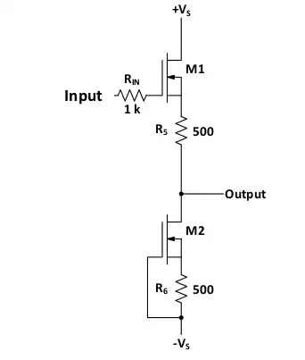
Here's en example illustrating the first problem. These two cases are going to measure significantly different amounts of power at Ant 2. They can be normalized, but only if you know the radiation pattern of both antennas.
enter image description here

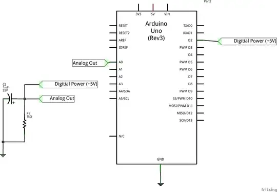
This cartoon shows how reflections (multipath) can impact the measured power level.
enter image description here

SteveSh
  • 9,672
  • 2
  • 14
  • 31
  • I have all the characteristics of the receiving antenna 2. I am using TRILOG Broadband Antenna as antenna 2. But I am performing the test in the open air and there will be lot of reflections as you mentioned. – Sai Dec 09 '21 at 08:03
0

The Friis transmission path-loss equation in decibels is this: -

$$\color{red}{\boxed{\text{Path loss (dB) = 32.45 + } 20log_{10}(f) + 20log_{10}(d)}}$$

Where \$f\$ is in MHz and \$d\$ is in kilometres.

So, if you take readings at various distances (2 might be enough) you should be able to factor out all the unknowns and get your answer. Clearly you should know the frequency in MHz so that part of the equation turns into a constant.

If you can gather this data but can't get an answer, report back.

Andy aka
  • 434,556
  • 28
  • 351
  • 777
  • With this formula, I found that the path loss in my case is 20.76 dB. I received the output power from antenna 2 of -90dBm. I am operating at 868 MHz and distance between both is 3m. Now, how could I find the output power from antenna 1? – Sai Dec 08 '21 at 16:08
  • Try at a distance of 6m. The path loss formula will tell you the extra loss and the difference in power values should then imply the originating power from the transmit antenna. – Andy aka Dec 08 '21 at 16:22
  • Now I kept distance of 6m as you said. Here I found that the path loss of 26.78 dB. I received the output power from antenna 2 of -101dBm. So, my transmit output power is -101+90 i.e., -11 dBm or -90+101 i.e., 11dBm? – Sai Dec 08 '21 at 16:40
  • Well, it's a good start because you have confirmed that you can effectively apply the Friis path-loss formula on this setup but, the output power is not -11 dBm or +11 dBm. What you need to do next is look at the data sheet for the transmit antenna and understand a little more about the radiation pattern in the direction you have in your setup. It should reveal an attenuation figure at a certain distance. That distance is usually/sometimes specified at \$1 \lambda\$. Then work out what the path loss is at \$1 \lambda\$. – Andy aka Dec 08 '21 at 17:21
  • You also need to factor in the antenna gains at both ends; that's simply taking into account in the PL formula that the -90 dBm reading you got at 3 metres is improved by a few dB due to antenna gains. – Andy aka Dec 08 '21 at 17:23
  • I am using a normal wire as antenna 1. I do not have any datasheet as it is simple wire with lambda/4 length. Is there any other way? – Sai Dec 09 '21 at 07:51
  • OK, it's a simple monopole then. It has a defined gain of about a couple of dB compared to an isotopic antenna so double check that. Then , calculate the aperture size of your receiver (I guess also a monopole) and theoretically you have what fraction of power it pulls from the air based on surface area of a sphere of radius equal to distance between transmit and receive antennas. That should get you closer. – Andy aka Dec 09 '21 at 08:28