The Very Short Version A.K.A tl;dr;
A transistor is needed to make tank circuits continually run. How does the transistor make tank circuit do this? Is it adding to the electric field of the capacitor or the magnetic field of the inductor. And what triggers it to do this?
The Medium version
I have three circuits mentioned below in the detailed version. All are tank circuits. When continuous power is supplied to one without a transistor it doesn't work. When a transistor is applied it works. Why does it work? Also, how does it work? Is the oscilating current coupled to the base of the transistor so it adds more power at the right time?
The Detailed version
I'm new to using this site so please bear with me.
Years ago I took a basic electronics course and I thought it would be interesting to get back into it. In regard to tank circuits, I understand the basic concepts of how crystal radio sets are able to convert the signal they receive into sound. However, for transmitting I know you can force your carrier wave to be on a frequency using a crystal oscillator, but for the last few days I've been trying to figure out how to keep a tank circuit powered up.
I have set up an example Here (click here for the live exciting version) I realize that these are by no means fine tuned. I'm sure more components could be added to make the circuits work better and/or have different values, but the goal is to have the simplest circuit to get oscillations to occur.
There are 3 circuits.
The first is a basic circuit with an inductor and a capacitor. When under constant power, the first scope shows there are no oscillations. When the switch is opened there are oscillations. From what I remember from class there will be some voltage on one side of the capacitor and the current will start to flow through the inductor. Inductors resist the change in current and as the electricity travels from one side of the capacitor to the other, the inductor will have a magnetic field built up. It continues to pull voltage from one side to the other until "all" (if resistance didn't exist) the voltage is on the other side. The process repeats in the opposite direction.
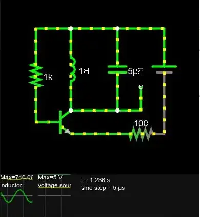
The second example is from an online circuit and it has been trimmed down so there is no amplitude modulations or frequency modulations, just a carrier wave. It is similar to the first circuit except there is a transistor in the mix. The 1st scope shows that there are oscillations. Now why this works, I don't really know. I'm suspecting that the base of the transistor is coupled in parallel to the inductor and it only allowing some extra current to "refill" the capacitor. However, the 2nd scope shows that this configuration is constantly pulling electricity through the transistor.(I'm sure a resistor could help slow this down some, but I want the circuits as simple as possible.)
The third example is more complex. I know that the two capacitors need to be changed in pairs to adjust the frequency. The 1st scope shows that it has more voltage going through the inductor than the second circuit and the 2nd scope shows that the transistor only fires when it needs a boost. It appears that this is the best design. I have no idea how it works, but I will venture a guess since my goal it to understand it. I think as power comes it the left hand capacitor is "charged up". Once it is full, current begins to flow through the inductor. The voltage from the left capacitor begins to flow to the right capacitor. If resistance didn't exist I would imagine that this circuit might just oscillate forever, but somehow the transistor is supplying a boost.
Well that is my best shot as to what is going on. I think I understand roughly how the "LC" part of the tank circuit is working, but if I'm wrong any help would be appreciated. The biggest part that I'm confused about is how the transistors are providing power to keep the circuit running. I think they are somehow providing a small boost at just the right time. I'm not sure if that boost is charging a capacitor or adding more current through the inductor at the right time which builds a little more magnetic flux to be converted into voltage into the capacitor. Thanks for the help!
Edit Added pictures per comment suggestions and make the question clear with a tl;dr;


