2

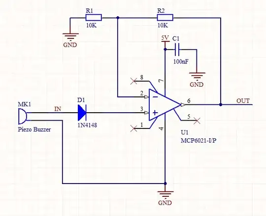
I'm using a piezoelectric speaker as an shock sensor. I made a simple non-inverting amplifier using the MCP6021 op-amp as shown in the circuit below. I'm only interesting in the positive output of the speaker so I put a diode to protect the op-amp's input from the negative spikes.

The circuit works as expected when the the oscilloscope's probe is connected to the input (either before or after the diode). When I disconnect the probe from the input, the output of the op-amp seems the become unstable. Sometimes it oscillates at different voltage levels and sometimes it saturates at the positive rail.

What could cause this behavior?

circuit

m.Alin
  • 10,638
  • 19
  • 62
  • 89
  • You don't show any load. Is OUT connected to anything? What do you have connected when you use just the oscilloscope? it seems perhaps the MCP6021 can't have low enough impedance (which would be a bit strange. – Gustavo Litovsky Mar 04 '13 at 16:28
  • @Gustavo The OUT isn't connected to anything except a second probe – m.Alin Mar 04 '13 at 16:32

2 Answers2

8

Connect a high value resistor from pin 3 = op-amp non-inverting input (OA+) to ground. 10 megohm may be OK but 1M better and lower still better still - but lower will load MK1 more.

What is [very probably] happening is that there is no DC bias to the OA+ input and in the absence of signal the very high impedance input is driven by a combination of inset-offset voltage, input bias current and the prior positive input - all stored in or charging or discharging the capacitance at OA+ to ground.

Oscilloscope probes and fingers (when connected to bodies) tend to make such arrangements work better or differently by providing a small amount of "ground reference" current or a degree of sink impedance.

Russell McMahon
  • 147,325
  • 18
  • 210
  • 386
4

I highly recommend adding a protection diode to prevent the piezo buzzer generating voltages outside the OpAmp's input spec. The piezo devices can easily do this.

Re: Russell's point about loading MK1 too much. Don't worry about it. I have used a very similar circuit, and I found that the output of the piezo device is surprisingly powerful, even with only a couple of K load resistors. I glued the piezo device to my bike, and it was able to detect the tiny vibrations caused when anyone touched it.

Piezo Vibration sensor

I think on this design I actually fiddled with the resistor values a bit to pull the + and - lines apart a little to make it less sensitive.

Rocketmagnet
  • 26,933
  • 17
  • 92
  • 177
  • Thanks, always helps to have some input protection! This particular piezo speaker ([it looks like this](http://www.teagueduino.org/png/ref_hw/piezo.jpg)) doesn't have a high output voltage, as far as I've noticed. The maximum output voltage I was able to generate through impact was 2-3 V – m.Alin Mar 04 '13 at 17:02
  • In your circuit, you're using the op-amp just as a comparator? – m.Alin Mar 04 '13 at 17:06
  • @m.Alin I've checked the output voltages of precisely such a device yesterday (see [this answer](http://electronics.stackexchange.com/a/59627/14004)), and it easily tops 11 Volts on gentle knocks. Did you check the voltages using an oscilloscope with peak-hold or equivalent settings? The voltage spikes are extremely short, but very high. A regular multimeter does not catch them. – Anindo Ghosh Mar 04 '13 at 17:06
  • @m.Alin - Yes, that's right. I just wanted to detect and vibrations, rather than measuring an analogue acoustic signal. – Rocketmagnet Mar 04 '13 at 17:10