I have an MPU9250 on my board and I wanted to change the yaw calculating axis after reboot depending on how this board is placed, like this:
So now i can rotate the yaw counting axis, thanks to the answer here. In the image below you can see board' deafult position and new position:
And swapped some values that are passing to Madgwick filter depending on the image:
void Process_IMU()
{
//read raw data
uint8_t data[14];
uint8_t reg = ACCEL_XOUT_H;
uint8_t mpu_address = MPU9250_ADDRESS_DEFAULT;
while(HAL_I2C_Master_Transmit(_MPU9250_I2C,(uint16_t)mpu_address,®,1,1000) != HAL_OK);
while(HAL_I2C_Master_Receive(_MPU9250_I2C, (uint16_t)mpu_address, data, 14, 1000) != HAL_OK);
/*-------- Accel ---------*/
Accel_x = (int16_t)((int16_t)( data[0] << 8 ) | data[1]);
Accel_y = (int16_t)((int16_t)( data[2] << 8 ) | data[3]);
Accel_z = (int16_t)((int16_t)( data[4] << 8 ) | data[5]);
/*-------- Gyrometer --------*/
Gyro_x = (int16_t)((int16_t)( data[8] << 8 ) | data[9]);
Gyro_y = (int16_t)((int16_t)( data[10] << 8 ) | data[11]);
Gyro_z = (int16_t)((int16_t)( data[12] << 8 ) | data[13]);
Accel_X = 10*(float)((int32_t)Accel_x - Accel_x_bias)/(float)accel_sensitivity;
Accel_Y = 10*(float)((int32_t)Accel_y - Accel_y_bias)/(float)accel_sensitivity;
Accel_Z = 10*(float)((int32_t)Accel_z - Accel_z_bias)/(float)accel_sensitivity ;
Gyro_X = (float)(((int32_t)Gyro_x - Gyro_x_bias)/(float)gyro_sensitivity)*M_PI/180.0f;
Gyro_Y = (float)(((int32_t)Gyro_y - Gyro_y_bias)/(float)gyro_sensitivity)*M_PI/180.0f;
Gyro_Z = (float)(((int32_t)Gyro_z - Gyro_z_bias)/(float)gyro_sensitivity)*M_PI/180.0f;
// Get data of Magnetometer
// Get_magnetometer();
// for default placement
// MadgwickAHRSupdateIMU(Gyro_X,Gyro_Y,Gyro_Z,Accel_X,Accel_Y,Accel_Z);
// for new placement
MadgwickAHRSupdateIMU(-Gyro_Z,Gyro_Y,-Gyro_X,Accel_Z,Accel_Y,-Accel_X);
}
And here is the MadgwickAHRSupdateIMU():
void MadgwickAHRSupdateIMU(float gx, float gy, float gz, float ax, float ay, float az) {
    float recipNorm;
    float s0, s1, s2, s3;
    float qDot1, qDot2, qDot3, qDot4;
    float _2q0, _2q1, _2q2, _2q3, _4q0, _4q1, _4q2 ,_8q1, _8q2, q0q0, q1q1, q2q2, q3q3;

    // Rate of change of quaternion from gyroscope
    qDot1 = 0.5f * (-q1 * gx - q2 * gy - q3 * gz);
    qDot2 = 0.5f * (q0 * gx + q2 * gz - q3 * gy);
    qDot3 = 0.5f * (q0 * gy - q1 * gz + q3 * gx);
    qDot4 = 0.5f * (q0 * gz + q1 * gy - q2 * gx);

    // Compute feedback only if accelerometer measurement valid (avoids NaN in accelerometer normalisation)
    if(!((ax == 0.0f) && (ay == 0.0f) && (az == 0.0f))) {

        // Normalise accelerometer measurement
        recipNorm = invSqrt(ax * ax + ay * ay + az * az);
        ax *= recipNorm;
        ay *= recipNorm;
        az *= recipNorm;

        // Auxiliary variables to avoid repeated arithmetic
        _2q0 = 2.0f * q0;
        _2q1 = 2.0f * q1;
        _2q2 = 2.0f * q2;
        _2q3 = 2.0f * q3;
        _4q0 = 4.0f * q0;
        _4q1 = 4.0f * q1;
        _4q2 = 4.0f * q2;
        _8q1 = 8.0f * q1;
        _8q2 = 8.0f * q2;
        q0q0 = q0 * q0;
        q1q1 = q1 * q1;
        q2q2 = q2 * q2;
        q3q3 = q3 * q3;

        // Gradient decent algorithm corrective step
        s0 = _4q0 * q2q2 + _2q2 * ax + _4q0 * q1q1 - _2q1 * ay;
        s1 = _4q1 * q3q3 - _2q3 * ax + 4.0f * q0q0 * q1 - _2q0 * ay - _4q1 + _8q1 * q1q1 + _8q1 * q2q2 + _4q1 * az;
        s2 = 4.0f * q0q0 * q2 + _2q0 * ax + _4q2 * q3q3 - _2q3 * ay - _4q2 + _8q2 * q1q1 + _8q2 * q2q2 + _4q2 * az;
        s3 = 4.0f * q1q1 * q3 - _2q1 * ax + 4.0f * q2q2 * q3 - _2q2 * ay;
        recipNorm = invSqrt(s0 * s0 + s1 * s1 + s2 * s2 + s3 * s3); // normalise step magnitude
        s0 *= recipNorm;
        s1 *= recipNorm;
        s2 *= recipNorm;
        s3 *= recipNorm;

        // Apply feedback step
        qDot1 -= beta * s0;
        qDot2 -= beta * s1;
        qDot3 -= beta * s2;
        qDot4 -= beta * s3;
    }

    // Integrate rate of change of quaternion to yield quaternion
    q0 += qDot1 * (1.0f / sampleFreq);
    q1 += qDot2 * (1.0f / sampleFreq);
    q2 += qDot3 * (1.0f / sampleFreq);
    q3 += qDot4 * (1.0f / sampleFreq);

    // Normalise quaternion
    recipNorm = invSqrt(q0 * q0 + q1 * q1 + q2 * q2 + q3 * q3);
    q0 *= recipNorm;
    q1 *= recipNorm;
    q2 *= recipNorm;
    q3 *= recipNorm;
}
Here is how I calculate φ, θ, ψ in main.c loop:
Process_IMU();

q[0] = q0;
q[1] = q1;
q[2] = q2;
q[3] = q3;
a12 =   2.0f * (q[1] * q[2] + q[0] * q[3]);
a22 =   q[0] * q[0] + q[1] * q[1] - q[2] * q[2] - q[3] * q[3];
a31 =   2.0f * (q[0] * q[1] + q[2] * q[3]);
a32 =   2.0f * (q[1] * q[3] - q[0] * q[2]);
a33 =   q[0] * q[0] - q[1] * q[1] - q[2] * q[2] + q[3] * q[3];
float sinp = a32;
if (abs(sinp) >= 1)
    pitch = copysign(M_PI/2,sinp);
else
    pitch = asin(sinp);
//pitch = -asinf(a32);
roll  = atan2f(a31, a33);
yaw   = atan2f(a12, a22) * 2;
pitch *= 180.0f / pi;
yaw = atan2f(sinf(yaw),cosf(yaw));
yaw   *= 180.0f / pi;
roll  *= 180.0f / pi;
So when I unload the program, everything work well and yaw is calculating as I expected:
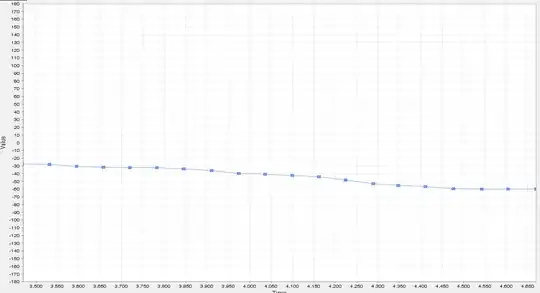
Until the moment when I slightly tilt the board along one of the axes and return it to its previous position:
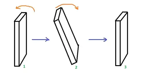
And after that when I try to rotate it around yaw axis (as I rotated before) it returns me very weird values. Even when I do not rotate the board it gives me the "noise":
What could be the reason of this? Thanks for any advice!
EDIT 1: I have checked out Accel and Gyro values and it seems, that they are correct:
I think that conversions are correct.
EDIT 2: I found where is the problem, but I don't know why doesn't it work as should. The problematic line is recipNorm = invSqrt(s0 * s0 + s1 * s1 + s2 * s2 + s3 * s3);. recipNorm starts from 0 and goes up to 500 and then recipNorm is very randomatic. I thought that problem is in invSqrt but I found somewhere stable invSqrt code:
int instability_fix = 1;

float invSqrt(float x) {
    if (instability_fix == 0)
    {
        /* original code */
        float halfx = 0.5f * x;
        float y = x;
        long i = *(long*)&y;
        i = 0x5f3759df - (i>>1);
        y = *(float*)&i;
        y = y * (1.5f - (halfx * y * y));
        return y;
    }
    else if (instability_fix == 1)
    {
        /* close-to-optimal  method with low cost from http://pizer.wordpress.com/2008/10/12/fast-inverse-square-root */
        unsigned int i = 0x5F1F1412 - (*(unsigned int*)&x >> 1);
        float tmp = *(float*)&i;
        return tmp * (1.69000231f - 0.714158168f * x * tmp * tmp);
    }
    else
    {
        /* optimal but expensive method: */
        return 1.0f / sqrtf(x);
    }
}
But I tested all of them and they work similary. I don't know what to do.
