-3

I am designing an Analog Front-End circuit for an NTC Sensor which has 3 parts, the non inverting stage, the low pass filter, and goes to seeeduino.
Basically the input voltage is 5Vcc and I need to have a voltage output from 0 to 5V.
The NTC is the negative thermistor that changes according to temperature. R1 is there to act as a voltage divider that helps comparing the voltage entering the inverting side of the OA.

Both R1 and NTC are 10k ohm.
NTC is 10k at 25ºC (ambient temperature).
The opamp is an MCP6004.
The NTC range is: 27119 ohm at 5ºC, 10k for 25ºC and 4103 for 45ºC. I also have the Steinhart-Hart coefficients if necessary.

Both NTC and R1 are 10K ohm.

Salah
  • 13
  • 3
  • hi. Where eactly are you stuck? What have you tried? From your photo, it's hard to understand what the problem you're solving even is! – Marcus Müller Nov 24 '21 at 20:19
  • @MarcusMüller i don't remember how to analyse the circuit in that part. i'm guessing thevenin? – Salah Nov 24 '21 at 20:21
  • 1
    @RodrigoMarinho analyse for what? Like, what are you looking for? And again, *where are you stuck? "how to know these resistors" makes no sense without stating what the goal of all this is – we really can't look inside your head and understand what you're trying to achieve. – Marcus Müller Nov 24 '21 at 20:25
  • @RodrigoMarinho You can find a general approach to this kind of problems in this old-ish answer of mine: https://electronics.stackexchange.com/questions/156719/opamp-inverting-amplifier-the-case-of-non-inverting-input-not-being-connected-t/156723#156723 – Eugene Sh. Nov 24 '21 at 20:34
  • @MarcusMüller i am designing an Analog Front-End circuit for NTC Sensor, which has 3 parts, the non inverting stage, the low pass filter, and goes to seeeduino. Basically the input voltage is 5Vcc and i need to have a voltage output from 0 to 5V. That NTC there is the negative thermistor that changes according to temperature. The R1 is there to act as a voltage dividir that helps comparing that voltage entering the negative side of the OA. I had eletronics class about 3 years ago and i dont remember how i could analyse those R3 R4 R5 R6 so that i can have this vo=(v+)+(v-). – Salah Nov 24 '21 at 20:35
  • @EugeneSh. thanks a lot for your help, [Edited by a moderator.] – Salah Nov 24 '21 at 20:36
  • It sounds like you're trying to design a circuit and you're trying to figure out what resistor values you need in order for the circuit to behave correctly. Am I understanding you right? – Cassie Swett Nov 24 '21 at 20:38
  • @TannerSwett sorry for my desperate and almost no information question but yes! i epxlained what i wanted a few answers up! – Salah Nov 24 '21 at 20:39
  • 1
    With the given information, all we know VCC is 5V and you want 0V to 5V out. But if you don't give what voltages go into op-amp, nobody can calculate how to get 0V to 5V from that. If the op-amp can even work with such voltages. – Justme Nov 24 '21 at 20:47
  • @Justme we know NTC and R1 – Salah Nov 24 '21 at 20:50
  • @RodrigoMarinho We don't unless you edit that info in. We also don't know what temperature range you need, to know the NTC resistance range, to know what input voltage range there will be for the opamp input. And we don't know the op-amp type. So basically, we don't know what the op-amp output voltage should be at some temperature. – Justme Nov 24 '21 at 20:53
  • @Justme the ampop is MCP6004. the NPC range is: 27119 ohm to 5ºC, 10k for 25ºC and 4103 for 45ºC. I also have the steinhart hart coefficients if necessary. – Salah Nov 24 '21 at 20:56
  • @RodrigoMarinho - That's the temperature characteristics of your NTC thermistor. You have not specified what temperature range you want to measure and map to a 0-5V output. What temperature should 0V represent, and what temperature should 5V represent? – brhans Nov 24 '21 at 21:06
  • @brhans I know that lmao thought thats what he was asking. that will depend on the whole circuit – Salah Nov 24 '21 at 21:09
  • 2
    All - Now that the OP has explained what they know and clarified where they are stuck then, irrespective of whether this is actual homework or not, it meets the minimum criteria. Therefore earlier comments about that (and about a video call request etc.) will be deleted as obsolete. Remember everyone - *Be Nice*. Thanks. – SamGibson Nov 24 '21 at 21:11
  • 1
    @RodrigoMarinho - no, you have it backwards. The values for R3, 4, 5 & 6 depend on what you're trying to measure. You need to decide what range you're trying to measure before those resistor values can be calculated. *And you still haven't told us what range you're trying to measure!* For all we know you want to measure between 23C and 77C, or -12C and 36C, or any other range. The specs you've quoted for your thermistor do not determine the range you're trying to measure. – brhans Nov 24 '21 at 21:14
  • I suggest you get a simulator like LTspice and try yourself. You'll learn much by experimenting. – Sim Son Nov 24 '21 at 21:27
  • @brhans i though those were the values I told you and respective resistance values. the 5 25 and 45ºC. These 3 values were chosen by me, so that's my range, 5 to 45.In the datasheet it went from -50 to 120. – Salah Nov 24 '21 at 21:40
  • @brhans my main doubt here is how i analyse that part of the circuit, to have Vo in function of V(-). – Salah Nov 24 '21 at 21:43

2 Answers2

1

Your input is a voltage divider consisting of R1 and the NTC thermistor and fed with a 5V supply.
You've specified that for the 5ºC to 45ºC temperature range you're interested in, the resistance of your thermistor changes from 27.119k to 4.103k.
So, simple voltage-divider math tells us that the output from your voltage divider to the the opamp will be 1.35V to 3.55V - a range of 2.2V.

So the function you need from your opamp circuit is (approximately):
\$ Vo = 2.25(Vi - 1.35) \$
I've taken some liberties with rounding because resistor tolerances will introduce far more error than the rounding

The 'ideal' circuit (if you had a fixed reference to use) would then simply be one with a gain of 2.25, using the reference to offset the value.
So the ratio of gain-setting resistors for a simple non-inverting configuration would be 1.25:1, since:
\$ Ao = 1 + (Rf / Ri) \$
      \$ = 1 + (1.25 / 1) \$
      \$ = 2.25 \$
and the reference you'd need would be:
\$ Vref = 1.35 + (\frac{1.35}{1.25k} \cdot\ 1k) \$
          \$ = 2.43V\$

So your resulting circuit might look something like:

schematic

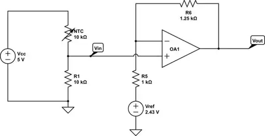
simulate this circuit – Schematic created using CircuitLab

However you don't have a 2.43V reference - all you have is your 5V supply.
So what you can do instead is combine the 2.43V reference with the R5 resistor to produce an equivalent using your 5V supply and a fixed voltage divider.
To get 2.43V from 5V using a voltage divider you need a ratio of 1.056:1. And the parallel combination of resistors needs to be equal to 1k (or whatever value you end up choosing for R5).
For this 'ideal-ish' example, I'll choose resistor values of 1k94 and 2k06, which gives me 2.425V and 0.999k.
The circuit now looks like this:

schematic

simulate this circuit

and produces roughly the same result as the previous version using the reference voltage.

However, these are not realistic resistor values.
To produce a more realistic circuit, I now start working backwards from where we are.
A pair of 'realistic' resistor values to use in a voltage divider which will give us about 2.43V from a 5V supply could be 5k1 and 4k7. This combination will actually give us about 2.4V.
That pair of resistors in parallel is about 2.45k - so the feedback resistor for the opamp needs to be 3k06 (2.45k x 1.25), so we'll choose 3k as a realistic value.
So now we have a circuit which looks like this:

schematic

simulate this circuit

If you do the math or run the simulation, you'll find that this circuit now produces an output of approximately 0.06V to 4.95V for a temperature range of 5ºC to 45ºC.

brhans
  • 14,373
  • 3
  • 34
  • 49
  • Amazing explanation. Thank you so much I understood it all finally. Solved! – Salah Nov 24 '21 at 22:51
  • shouldn't R6 be much larger than R4 to avoid loading the voltage divider? – Marcus Müller Nov 24 '21 at 23:03
  • @MarcusMüller - no, you're intentionally loading the voltage divider in this circuit because it's not acting as a simple voltage divider - it's actually part of the opamp's gain-setting too. – brhans Nov 25 '21 at 01:13
  • If you wanted to treat it as a simple voltage divider then yes, you'd increase R6 by 1 or 2 orders of magnitude and then also insert another resistor between the divider and the non-inverting input (R5 in the OP's original circuit) to set the gain along with R6. – brhans Nov 25 '21 at 01:17
0

This breaks down into the following parts, which you need to do, step by step:

  1. Realize that your NTC + R1 form a voltage divider, which is connected to the non-inverting input of the opamp.
    1. Thanks to your info on the temperature range \$\Delta_T\$ you want to map to 0-5V, we can now calculate the resistance range the NTC will have.
    2. With that resistance range, we can calculate the voltage range at the non-inverting input of the opamp. Let's call that voltage rang \$\Delta_V\$.
  2. You know that your output voltage range needs to be 5 V, but you only get \$\Delta_V\$ of range on the input, which is less than 5V. So, that defines the gain \$A\$ your opamp needs to have.
  3. After applying the gain, the minimum voltage over the voltage divider \$V_\min\$ gets scaled to a voltage that's not 0V. So you need top subtract that offset, to shift your \$A\cdot V_\min\$ to 0 V. I.e., your offset \$B\$ needs to fulfill \$A\cdot V_\min+B = 0\$.

Now, the gain can be implemented simply by considering only the feedback resistor \$R_6\$, and a resistor to ground from the inverting input. If we imagine very hard that instead of \$R_3\$ and \$R_5\$, the non-inverting input, and \$R_6\$ & \$R_4\$, are directly connected to ground, we get the gain \$A=1+\frac{R_6}{R_4}\$. Nice! That's the first equation for our resistors; insert the \$A\$ you calculated from the voltage range relation above!

The offset \$B\$ can be achieved by not connecting to ground, but to a different voltage (the opamp simply doesn't care to which voltage it refers to). So, \$R_3\$ with \$R_4\$ gives us another voltage divider, which gives us a voltage that we can refer to as virtual ground.

Problem: This is a loaded voltage divider, so it won't work as good. This is only solvable by making the current flowing through the voltage divider in unloaded state (so, with \$R_5\$ imagined removed) much lager than any load current. Therefore, \$R_6, R_5 \gg R_3, R_4\$. But the simple voltage formula, which needs to generate \$B\$ from 5V, will then give us the second equation for our resistors.

Eugene Sh.
  • 9,986
  • 2
  • 26
  • 41
Marcus Müller
  • 88,280
  • 5
  • 131
  • 237