If you do not SHOW the exact circuit and connections that YOU are using then ALL questions of this sort are pointless.
This is the circuit diagram accessed via the page you referenced. Please add YOUR connections to it and post as part of your question.
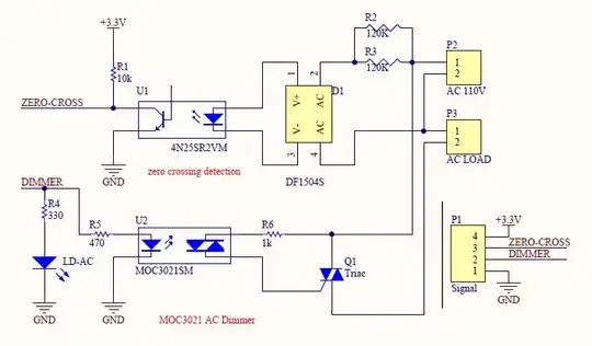
Arduino ground MUST be connected to MOC3021 ground.
NB!!! - The following highlights a defect in the design of the circuit. This may or may not be what is wrong with your circuit. eg they may have found that the MOC3021SM did not work reliably and substituted a MOC3023 or MOC 022. Your problem MAY be unrelated.
Using a wire connect 3.3V+ to Dimmer input pin.
Triac should operate and drive load.
If 1. works, connect 3.3V+ at Arduino drive output pin connection. Ideally you should remove Arduino pin connection as this MAY damage the Arduino. In almost all cases it should be OK but back feeding 3.3V into a low driven in is "naughty" at best.
TRIAC should operate.
If 1. & 2. do not work the problem could be circuit as below or still your fault.
Change R5 as below and retry 1 & 2.
When Arduino high OR +3.3V is connected to Dimmer in there should be a voltage drop across R5 (very roughly 1.5V+ ) and U@ input pin should be at 1.2 - 1.5V above grpund.
The circuit has been badly "designed" and with 3.3V drive will not work with optocouplers meeting typical data sheet spec and is (of course) even worse with worst case data sheet spec. Even with 5V drive it will not meet typical spec.
The designer, if there was one, had severe brain fade the day this was designed.
MOC3021 data sheet - brand MAY matter, alas.
Opto input voltage at 20 mA = 1/15V / 1.5V typical / max .
Current to latch TRIAC = 8 / 15 mA typical/ max.
Working with TYPICAL opto vin and typical drive current (ie most optimistic case).
Iopto = (Vin - Vopto)/R5 = (3.3-1.15)/470 = 4.6 mA.
Typical optto current = 8 mA.
Worst case opto current = 15 mA !!!
Arduino drive current min = ??? mA.
For worst case R5 = (Vin-Vopto_max)/Imax = (3.3-1.5)/15 mA = 120 Ohm.
Vopto_max is at 20 mA but you MAY need most of 20 mA worst case.
What is the Arduino drive current capability max and what does Vhi drop to at this current.
Change R5 to 100 Ohms.
Or place 120 Ohms or 150 Ohms in parallel with R5.
8-15 mA
1.15-1.5V
(3.3-1.5)/470 =
ADDED
A question was asked about very low trigger current devices.
Use this search to see all Digikey zero crossing optocouplers, sorted by ascending trogger current. Ignoring thos for which Ift is not shown, the (Vishay IL411x family has the lowest Ift at 1.3 mA worst case. They say actual current used should be several times that, and show that trigger current varies with load voltage and temperature and more., Read data sheet for more information.
The Fairchild **FOD4xx and xxx family are similar.
The MOC3063 from Liteon and others has Ift = 5 mA. See data sheet for details.