7

I would like to hook up a piezoelectric sensor to my ATmega8 microcontroller via its ADC.

The reason being is that I would like to use the sensor as a force sensor. I noticed that the harder I press it, the higher a voltage it delivers (but for a very short time). This is expected behavior, of course.

What I am wondering is how I would connect it to the ADC. I mean, when I press it really hard, the piezo registers upward of 10 V. When I press it softly, it usually gives me around 1.3 V.

As I understand it, the micrcontroller cannot take anything more than 5V, or else I run the risk of damaging it. Is this correct? I mean, I am guessing the current coming out from the piezo is extremely small, though I don't know if that changes the situation.

Essentially, I would like to know if it is possible to hook up this piezoelectric sensor to my AVR microcontroller to take analog readings.
capcom
  • 5,882
  • 14
  • 48
  • 59
  • 2
    Depending on the pressure area-of-interest: If the low to moderate pressures are important, and high and higher are not, then a clipping circuit (zener shunt) or combination of voltage divider and clipping, might yield more relevant results. Basically, anything over a certain force will be a flat "high" value, while lower than that force will result in a nice analog value range. Also see [this question](http://electronics.stackexchange.com/q/55355/14004) for a similar application. – Anindo Ghosh Mar 03 '13 at 04:48
  • 1
    @AnindoGhosh That's a really, really great idea. Please leave it as an answer if you have a moment. Superb idea. – capcom Mar 03 '13 at 05:03
  • OK, I will, when I get back to a computer later today. Thanks. – Anindo Ghosh Mar 03 '13 at 05:49

3 Answers3

10

A quick experiment with a piezoelectric bender shows the following voltages:

  • No pressure: 0.12 Volts (probably drift / noise / breeze)
  • Mild pressure: 1.72 Volts
  • Firm pressure: 4.21 Volts
  • Fingernail tap: 6.29 Volts (spike)
  • Knock on table: 11.74 Volts (spike)

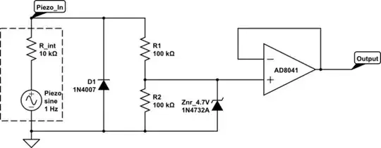
Assuming the area of interest spans the first 4 levels of signal, and any reading higher than 10 Volts can be generalized to an arbitrary "Out-of-Range" reading, the following implementation should serve for the purposes of question:

schematic

simulate this circuit – Schematic created using CircuitLab

The diode D1 shunts the negative portion of the signal that the peizo bender will generate on knocks or release of pressure. To be extra-cautious, this can be substituted by a Schottky diode to cope with very fast spikes, or for tighter clipping to ground rail (~ 0.3 Volts instead of ~0.7 Volts), a germanium diode.

The Zener diode is intentionally selected as 4.7 Volts, in order to ensure that the output voltage does not overshoot 5 Volts under any circumstances.

The op-amp buffer ensures that the voltage divider is not significantly loaded by the ADC pin, hence the voltage divider resistance computation is simplified.


This circuit will output half the positive voltage generated by the piezoelectric pressure sensor until the voltage reaches approximately 4.7 Volts, then clamp at that voltage for any higher pressures applied. Any negative voltage generated due to knocks or sensor bounce-back, will be shunted across the diode D1, protecting the op-amp (or the ADC if directly connected) from negative voltages.

Anindo Ghosh
  • 50,188
  • 8
  • 103
  • 200
  • What load did you have across the piezo when you did the voltage tests? If unloaded, it might be instructive to try 200 kilohms as drawn and re-check those voltages... –  Mar 03 '13 at 13:38
  • Neat answer. Though do you think you could explain the need for the op-amp a little more, please? I am not quite sure I understand why I need it. I understand the entire circuit otherwise. Many thanks. – capcom Mar 03 '13 at 13:52
  • @BrianDrummond I'm lazy: I had shunted the DSO lead with 220k, and that's why I kept those 100k values for the resistors, close enough and saved me calculating stuff :-) – Anindo Ghosh Mar 03 '13 at 14:17
  • @capcom The input impedance of the ATmega8 ADC pins is nominally 10 kOhms. If you were to apply said 10k across the voltage divider, it would throw the voltage divider off quite a bit. The final computations in Chetan Bhargava's answer would then apply, except that the actual input impedance of the pin is not constant nor precisely 10 kOhms. Using the buffer op-amp avoids this issue by presenting a very high effective input impedance to the voltage divider, while providing an output impedance much much lower than 10 kOhms to the ADC. – Anindo Ghosh Mar 03 '13 at 14:23
  • I see. I guess I need to understand what impedance is in order to better understand the reasoning. Unfortunately, I do not have an op-amp on hand. Does this mean I cannot use the piezo? Or would Chetan's answer still work, since it does make sense to me. Thank you. – capcom Mar 03 '13 at 16:09
  • You will need the buffer on the output shown in Anindo's circuit. Your ATmega doesn't have the input impedance to deal with a piezoelement. Your signal would appear very small without it. An op amp with a FET input would be best – Scott Seidman Mar 03 '13 at 16:30
  • @ScottSeidman Then how come, for example, this project works http://arduino.cc/en/Tutorial/Knock Wouldn't it exhibit the same problem? – capcom Mar 03 '13 at 17:22
  • @capcom If you notice, that project does not protect the ADC input, does not voltage-divide, and entrusts the high output impedance of the piezo for limiting adverse effects. – Anindo Ghosh Mar 03 '13 at 18:58
  • Well, since I do not have an op-amp, it wouldn't hurt to try that, no? I will voltage divide, and use a zener diode (to ensure I don't feed it more than 5V) or give it a reverse voltage. That's the best I can do with what I have. Do you think it will still work, just not as effectively as your suggestion? Thanks. – capcom Mar 03 '13 at 19:09
  • @capcom With anything being attempted out of spec, the only advice anyone can give is: Try it, and if the magic smoke doesn't come out, it's all good :-) – Anindo Ghosh Mar 03 '13 at 19:40
  • Yikes, why would there be magic smoke here? I'm not using anything high power. As far as I see it, it just wont work. I don't think I'd be risking my MCU, right? – capcom Mar 03 '13 at 19:41
  • @capcom You won't know until you try. As you'll hear from many who've been _burnt_ before, surprisingly little voltages can cause the smoke effects, and yet sometimes a part can take surprisingly high levels of misuse and survive. – Anindo Ghosh Mar 03 '13 at 19:44
  • 2
    If you go to the data sheet for the microcontroller you're using, the Absolute Maximum Rating for Voltage on any pin is Vcc + 0.5V. If you exceed that, the manufacturer does not guarantee that the chip will ever work again -- by definition. If it still works, it still works, but don't be surprised if it doesn't. – Scott Seidman Mar 03 '13 at 21:32
3

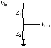
You can use a resistor divider to scale the input voltage. The divider is simply based on Ohms Law.

divider

Above circuit is taken from wikipedia article on the subject. In the above case Vin should be connected to the piezoelectric sensor and Vout should be connected to your ADC input.


divider2

The above circuit is taken from the divider calculator. You can use the calculator here to calculate the values of resistors.

Chetan Bhargava
  • 4,612
  • 5
  • 27
  • 40
  • How could I have been so stupid? Wow, thanks. I think I need to sleep now. – capcom Mar 03 '13 at 04:20
  • @capcom If you're interested in a voltage divider calculator that uses standard values instead of hypothetical ones, [check this out](http://howardtechnical.com/voltage-divider-calculator/). – TimH - Codidact Mar 26 '15 at 19:12
0

You can connect the clipper circuit with piezo element. Because, piezo element has generate the ac signal so may be it can reach maximum level at positive side or at negative side and we can able to detect at which impact it can rich the maximum level of voltage. So you can connect the clipper circuit and in that clipper circuit you can use germanium diode (0.3v clip) or silicon diode (0.7v clip), which is clipping the signal at negative and positive. So you can clip the signal and protect you controller.