I want to invert, difference, and amplify the 11.3-12V decaying (upwards to 12V) signal from the metal detector coil in the circuit at https://www.lammertbies.nl/electronics/pi-metal-detector into a 0-5v range signal compatible with microcontroller ADCs.
I looked at Level shifting a +/- 2.5V signal to 0 - 5V and the answers there, especially the https://electronics.stackexchange.com/a/37096/30711 which contains the only example of an inverting level shifter I've found, but since I want amplification and the input signal is not centered on zero, my use-case seems a couple steps more complicated.

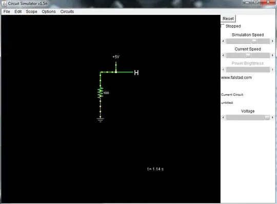
simulate this circuit – Schematic created using CircuitLab
I figure that this will clip with 0+-2.5V on the output, but I'm not quite sure how to inject an offset to push it up an additional 2.5v.
Do I sum in another voltage on the negative input?
Or would I adjust the positive input to something else?
===
For clarity, I'd like for the circuit to do approximately V_out = (12-V_in) * 7. I make plenty of sign and order of operations errors in my day job, and I'm curious how to translate this operation into an opamp. My attempt above seems like it would do V_out=(12-Vin)*7+(12V+0V)/2
Some completely fabricated curves of simulated input and desired output are below.
# R code:
x=0:30/1000
y1= 12-0.7* ifelse(x < 0.010,1,exp(-200*(x-0.010))); plot(x,y1,'l',col='black')
y2= 12-0.7* ifelse(x < 0.008,1,exp(-250*(x-0.008))); lines(x,y2,'l',col='red')
y3= 12-0.7* ifelse(x < 0.012,1,exp(-150*(x-0.012))); lines(x,y3,'l',col='blue')
y1= 7*0.7* ifelse(x < 0.010,1,exp(-200*(x-0.010))); plot(x,y1,'l',col='black')
y2= 7*0.7* ifelse(x < 0.008,1,exp(-250*(x-0.008))); lines(x,y2,'l',col='red')
y3= 7*0.7* ifelse(x < 0.012,1,exp(-150*(x-0.012))); lines(x,y3,'l',col='blue')
Simulated sample transient input voltages:

Simulated sample transient output voltages:

