1

I saw a simple transistor amplitude modulator circuit on the Internet (image attached below).

I have to build a simple amplitude modulator circuit using a transistor for my school project. I understand the concept that the signals are mixed and the transistor acts as a diode and rectifies due to the emitter-base junction, while the LC circuit oscillates to produce the other half of the modulated signal.

Now, how should I calculate the value of Vcc as well as the resistor at the emitter? I understand the frequency of the LC circuit should be the same as the carrier frequency, in my case 50MHz (my professor wants to modulate a high frequency).
enter image description here

ocrdu
  • 8,705
  • 21
  • 30
  • 42
Eddy Miner
  • 61
  • 7
  • 1
    In some ways you are getting closer to a old-time plate modulation circuit (the collector tank.) That's good. And yet a lot further away from a practical circuit (your stacked supplies.) Is this something you need to actually build? Or is this just some kind of cyborg (cybernetic organism) -- half reality, half simulation, thing? – jonk Nov 15 '21 at 07:59
  • @jonk I face quite many problems in order to solve this project. So I have to try any ways that I saw... Btw, the circuit simulated works well. – Eddy Miner Nov 15 '21 at 08:03
  • Okay. Kind of vague and, well, I don't really see how I can help here, so far. I'll leave it to others to worry over. Thanks for your time. – jonk Nov 15 '21 at 08:08
  • As you have two SERIAL generators, it can be an "additive" mixer and then it is the non linearity (exponential curve) of the BE junction that dictates the behavior. But if the signals are bigger, then it became a "multiplier" mixer (switching base current) ... which is a "different" behavior. – Antonio51 Nov 15 '21 at 09:00
  • Try running this circuit in the Falstad circuit simulator and you'd quickly come upon the right values. – ee_student Aug 17 '22 at 09:16

1 Answers1

1

The schematic is a "additive" mixer, but with these circuits, you have also many spurious. See the harmonic analysis. So, it is not pure AM.

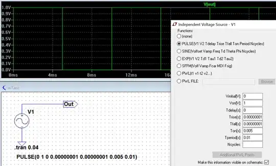
For "multiplying" mixer, one might consider that "carrier" is a square wave function (+1, 0), as in balanced 4 diodes mixer.

enter image description here

Just modified value of inductor for "improving" wave voltage.

For weak signals, see also my answer this post, same method : Hearing the radio by touching a jack plug

Do you see the difference ? (see current waveform).

enter image description here

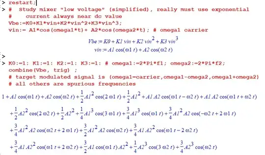
Here is Maple sheet example :

Be aware that for carrier \$omega1\$ (for example), some terms are involved ...

i.e. \$cos(omega1*t) * (A1 + 3/2*A1*A2^2 + 3/4* A1^3)\$

Modulation creates also a displacement of "Quiet Point" -> \$1+ 1/2*A1^2+1/2*A2^2+ ...\$

enter image description here

Antonio51
  • 11,004
  • 1
  • 7
  • 20