2

Given a reference voltage level, I need to pick the difference with respect to that reference, amplify it and then convert it to digital. (Yes, I want to measure small voltage drops between two lines).

I'm trying to achieve this by using a OPA379AIDCKR (https://www.ti.com/general/docs/suppproductinfo.tsp?distId=10&gotoUrl=https%3A%2F%2Fwww.ti.com%2Flit%2Fgpn%2Fopa379) in the following configuration:

schema

My simulation result:

enter image description here

As you can see I'm not able to make it work since the computed output should be (2.2)*(V+ - V-) = 0.66 V. Instead the simulation saturates.

I've tried with many resistance values and different configurations, but I always see the same. What did I do wrong? Is there something I'm missing?

PS: Spice model taken from manufacturer's website.
dew54
  • 21
  • 3

3 Answers3

4

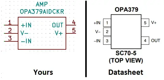
Your symbol pinout order does not match the model's pinout order. Here is the relevant section in your OPA379.LIB file:

* END MODEL FEATURES
*
* PINOUT ORDER +IN -IN +V -V OUT
* PINOUT ORDER  1   3   5  2  4
*
.SUBCKT OPA379 1 3 5 2 4
*
Q21 25 26 24 QNL
R77 27 28 200
R78 29 28 200
R79 30 26 100

Notice how the order is listed as: +IN -IN +V -V OUT ? Well, your symbol needs to match this order. It does not, but KiCad/Eeschema has an option to help you in dealing with this problem within the "Spice Model Editor". It is called "Alternate node sequence" and is found at the bottom of the second tab. This allows you to shuffle the symbol's pin order so that it matches the SPICE model/subcircuit. In this specific case, you want to set it to 1 3 5 2 4, as shown below.

enter image description here

Ste Kulov
  • 3,771
  • 10
  • 22
2

There is something wrong with the model and/or symbol, perhaps the connections to inputs are reversed. It should work, at least within a few mV at the output.

Spehro Pefhany
  • 376,485
  • 21
  • 320
  • 842
0

Your pins are in the wrong circular sequence:

OPA379

Audioguru
  • 3,894
  • 5
  • 8