1

I am having a hard time understanding how to pick resistor values to get the circuit to run. I think I have the basic design down correctly but feel like my resistor values are wrong. I calculated \$f_0\$ to be 8.7 MHz with 20 pF capacitors and 33 \$\mu H\$ inductor.

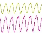
Here is the waveform:

Update: Adding a \$20 k\Omega\$ resistor right after the 5 Vdc gives me a way better looking output. Still not sure if this is correct though.

:

Geno C
  • 331
  • 3
  • 15
  • You seem to have omitted the component labeled RFC from the circuit shown in your book. That's a Radio Frequency Choke. It should be 10k ohms or higher at the frequency of oscillation. You see without that, your feedback path (from the top of the LC 'tank' back to the transistor base through C1) is tied to an AC ground; it may be at 5V DC, but effectively you have C3 shorted out. Sticking a resistor in that spot isolated that node from ground but also adds negative feedback. Try an inductor of 1mH or more, see what happens. – JustJeff Nov 24 '21 at 11:36
  • Thank you, @JustJeff! I really appreciate it. God, is electronics hard.. There is just so much to learn.. I graduate college in electrical engineering at the end of summer and I just feel so behind.. – Geno C Dec 07 '21 at 21:53

1 Answers1

1

I think I have the basic design down correctly but feel like my resistor values are wrong.

Your bias resistors are fine but, that isn't a Colpitts oscillator. There is no feedback to the emitter or base that sustains the oscillation. This is a common emitter Colpitts oscillator in case that is what you were designing: -
enter image description here

Picture from this Q and A. Note that the L and Cs are in the feedback path to the base and thus will sustain oscillation at the desired frequency. The above circuit is for approximately 2 MHz. Here are the three main types: -

enter image description here

The middle one is as per my earlier picture. This image from this Q and A. The left image is the common base Colpitts oscillator and the right image is the common collector Colpitts oscillator.

And, here is the theory of a common emitter Colpitts oscillator.

Adding a 20kΩ resistor right after the 5 Vdc gives me a way better looking output. Still not sure if this is correct though.

It may be oscillating but it's not oscillating as a colpitts circuit. In effect, the 20 kΩ allows some feedback voltage back to the base but not in a controlled way and, the operating frequency will vary with supply.
Andy aka
  • 434,556
  • 28
  • 351
  • 777
  • Thank you for the detailed answer. However, I wonder why I am able to get a decent looking output when I put a 20 k resistor in front of the DC power source.. – Geno C Nov 08 '21 at 07:26
  • Well, it looks more like 5 MHz to me so, if you designed it to be 8.7 MHz, it's not right. You need proper controlled feedback and not just randomly created feedback by adding components and hoping for the best. In other words, fix your circuit as per the diagrams in my answer. – Andy aka Nov 08 '21 at 07:30
  • Alright thanks for the updated answer, I'll try re-designing it. It's interesting because in my textbook, my design is identical, the only think that is different is instead of a 20 k resistor there is a RFC in front of the Vcc.. – Geno C Nov 08 '21 at 07:30
  • I can't see your book but I can tell you that the circuit in your question **does not** have positive feedback that allows oscillations to be sustained. – Andy aka Nov 08 '21 at 07:33
  • Just put a picture of it in the question. – Geno C Nov 08 '21 at 07:35
  • The RFC is a gamechanger. Without it, there is no feedback to sustain oscillations; with it being there, both base bias and base signal come through RB1 and sustain oscillation. Mind you; it's a pretty archaic version of a Colpitts oscillator because it requires two inductors and the whole point about the Colpitts oscillator is that it uses one inductor and shouldn't need an RFC. – Andy aka Nov 08 '21 at 07:51
  • Let us [continue this discussion in chat](https://chat.stackexchange.com/rooms/131246/discussion-between-geno-c-and-andy-aka). – Geno C Nov 08 '21 at 07:52
  • It seems like my resonant frequency has now shifted to 6.2 MHz, so I am unsure how to fix that. – Geno C Nov 08 '21 at 08:51
  • See comment in chatroom thread @GenoC – Andy aka Nov 08 '21 at 10:01
  • @GenoC are we all done here now? – Andy aka Nov 09 '21 at 13:42
  • read comments in chat. – Geno C Nov 09 '21 at 23:25