1

I'm trying to compensate a flyback boost circuit.

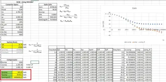
Unfortunately I seem to be failing to make the gain of the system ever cross 0 dB. I feel like I'm missing something obvious... Like a pole? I'm following the app note for the PMIC I'm using, so I feel like I'm not to far off. It seems like my output capacitance / ESR could be the issue? I have never run into it, but is there a case that the ESR / Capacitance combination is such that you can not achieve loop stability?

System is a 24 to 360 V flyback converter, operating in DCM. I have 2x 22 uF ~5 ohm aluminum capacitors on the output. I made another sheet with a composite AL capacitor and a 1 uF film, it did not help convergence...

I have a pole zero from capacitor, load and ESR. I then have the comp type 2 poles and zero... I also have the option to add feed forward, but right now made the values insignificant.

enter image description here

Update: Thanks for all the advice, I also found I was missing a pole in my calculations for compensation... So once this was fixed, I was able to get to a marginal stability. Still some work to do with a feed forward and modeling the parasitic capacitance on my feedback network (~720k creates a good LPF unfortunately...)
enter image description here

MadHatter
  • 3,506
  • 1
  • 19
  • 45
  • You need feed-forward comp. and might also want lower ripple using low ESR caps < 1 ohm or Fsw/RoutC << 1 – Tony Stewart EE75 Oct 30 '21 at 02:04
  • @TonyStewartEE75 Thanks, I was thinking that, but I was struggling to calculate the pole/zero combo. I'll do some reading and take another swing. – MadHatter Oct 30 '21 at 02:26
  • 3
    Try to have a look at my seminar [The Dark Side of the Flyback Converter](https://cbasso.pagesperso-orange.fr/Downloads/PPTs/Chris%20Basso%20APEC%20seminar%202011.pdf), there is a section on compensation. My seminar [Designing Compensators for Switching Power Supplies](https://cbasso.pagesperso-orange.fr/Downloads/PPTs/Chris%20Basso%20APEC%20seminar%202010.pdf) should also help. You have the DCM TF it in my last [book](https://www.amazon.com/Transfer-Functions-Switching-Converters-Christophe/dp/1949267512/ref=sr_1_14?dchild=1&keywords=basso&qid=1619591234&s=books&sr=1-14). – Verbal Kint Oct 30 '21 at 07:17
  • Flyback is a misnomer. They should be called Flybite as in bite yerass when hidden parasitics are not damped with RC//RCD+R clampers with TVS+D and consider ZVS too added. Low ESR caps also add instability at light loads from loss of load damping effects. – Tony Stewart EE75 Oct 31 '21 at 17:14
  • @TonyStewartEE75 - I usually add RC dampers, and I find a well designed transformer has low enough parasitics that the RC system works will with minimal loss... – MadHatter Oct 31 '21 at 17:24
  • Is that for <=25 W? With what phase margin? – Tony Stewart EE75 Oct 31 '21 at 17:36
  • No, I have done it with 60W fly-backs, Just S wind the transformer and the ringing on the primary FET is typically 2 orders of magnitude above switching... Most of my designs are 12/24/48V step-ups, not offline... The HV FETs may have worse parasitics that reduce the ringing frequency... And soon mods are going to move this to chat... Since comments are not for extended discussion. :) – MadHatter Oct 31 '21 at 17:40

1 Answers1

0

Try reducing the ESR of the output capacitor by parallelizing 2 ore more low ESR capacitors.

I use UCC United Chemicon aluminum electrolytic capacitors.

I noticed that NXP makes a lot of power supplies reference designs using UCC capacitors. NXP almost always publishes EMI signatures of their reference designs which are always EMC compliant due to the low value of ESR of UCC capacitors.

The lowest ESR value is achieved by using this kind of filter when selecting:

  1. Aluminum electrolytic. No polymer, no polymer hybrid

  2. Through-hole part. SMD is no good because ESR is pretty high.

  3. High voltage rating. In your case greater between 400 V and 500 V

  4. High ripple current. Greater than 750mA rms @ 105℃ @ 120Hz

  5. Minimum lifetime of 3000 hours @ 105 degrees

  6. Biggest size

Here you find a selection at Digikey:

https://www.digikey.com/en/products/filter/aluminum-electrolytic-capacitors/58?s=N4IgjCBcpgbFoDGUBmBDANgZwKYBoQB7KAbRAGYBOAJmoHYAOEAq686gBhAF0CAHAC5QQAZQEAnAJYA7AOYgAvgQCs1BCGSR02fEVIUGDesp78hkURJnylIWJXWbtuAsUhkALGDANKdUyCCwmJScooEYJS%2BjqiYLnruIFy8geaWoTYEnHQO0BqxOq76HhwcAAQAaswgXsqV1R6c9QQeJc01yuVVLXR13SCdXQFBFgCq0pICAPIoALI4aFgAruI4irZqiRiEAO5lOFjiZYhofGiIk4TiWDwKQA


I suggest you to reach an ESR below 1 Ohm


Stabilize first the circuit and then try to reduce the output voltage ripple. You may have to add by a secondary LC filter.

Enrico Migliore
  • 4,161
  • 1
  • 9
  • 12
  • Thanks Enrico, I already have 2 capacitors in series, and unfortunately many higher voltage capacitors do not spec ESR, although the ones that do seem to be anywhere from ~1 to 10 Ohms, So I am assuming a conservative 5 Ohms on my unrated ones. – MadHatter Oct 31 '21 at 16:37
  • Forward converters can use ESR*C = <10us Yet @VerbalKint 's slide show uses ESR*C = 100us on p155 for 1stage LED with 2.2mF with 50V 2.4A string – Tony Stewart EE75 Oct 31 '21 at 17:33