3

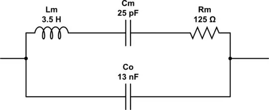
In this example of a model for a piezo element, there is an inductive component (I think this is a quartz crystal model -- it should not matter for the question. This graphic was also used here and here):

enter image description here

As the piezo vibrates, there are two forms of energy storage going on... capacitive, and inductive (or something like inductive). I believe that the inductive component comes from the piezoelectric effect, which relates electric field across the ceramic to its expansion on one side, and contraction on the other side. But there is also a mass-related momentum storage-of-energy involved, which means that we can increase the amount of energy that can be stored (at a particular voltage, 50% duty cycle, square waveform, lower frequency). Can I add a small weight to the vibrating mass, thereby increasing the stored "inductive" energy? (or what I'm hoping is the inductive component). And are there any other ways to do this, like adding stiffness (a little), springs on both sides, or connection to a tuning fork tine?
MicroservicesOnDDD
  • 2,557
  • 1
  • 13
  • 48
  • What are you exactly trying to get? Increase amplitude? Reduce resonance frequency? What picture just a model. – user263983 Oct 28 '21 at 16:29
  • @user263983 - How would I test this principle out? – MicroservicesOnDDD Oct 28 '21 at 17:19
  • It is not a principle, it is a model, abstraction. – user263983 Oct 28 '21 at 18:15
  • @MicroservicesOnDDD Perform some analysis for us about what you have there. Not just asking us questions by waving hands around in the air. What do you think about the solid state physics of a crystal structure and how energy might be stored in it? What would that actually *mean*? Do you know about phonons (the model, anyway), for example? How many different ways can energy be stored in a bit of solid state matter in crystal form? What is the resonant frequency of your model there? What is the impedance of each element? Etc. Put some stuff down on paper for us. Then ask questions. Please. – jonk Oct 28 '21 at 18:39
  • In a *crystal resonator*, grinding down thickness **raises** frequency, adding mass **lowers** frequency. Common oscillating mode for crystal is thickness-sheer - who knows what ceramic piezo modes exist? – glen_geek Oct 28 '21 at 19:02
  • _"we can increase the amount of energy that can be stored (at a particular voltage, 50% duty cycle, square waveform, lower frequency)"_ - yes, but why would you want to do this? – Bruce Abbott Oct 28 '21 at 19:53
  • Did U choose 17 kHz for this Piezo or just arbitrary – Tony Stewart EE75 Oct 28 '21 at 21:15
  • 1
    You need to attach a mechanical impedance matching device to match the mechanical impedance of the transducer to the impedance of the medium (I'm guessing air for your case) if you want to make it more efficient. This can be a thin diaphragm which is commonly done in little beepers. – qrk Oct 28 '21 at 21:51
  • @TonyStewartEE75 - It was just arbitrary. I recycled the graphic from 2 other answers. – MicroservicesOnDDD Oct 28 '21 at 21:54
  • @BruceAbbott - You asked me, "yes, but why would you want to do this?" And my answer is... For just a tiny slice of this pie: "[The global demand for piezoelectric devices was valued at approximately US$21.6 billion in 2015.](https://en.wikipedia.org/wiki/Piezoelectricity#Application)". – MicroservicesOnDDD Oct 29 '21 at 00:50

2 Answers2

4

Piezos are electromechanical transducers. That means that they are literally a bridge between the electrical and mechanical worlds. The series LCR circuit in your diagram is the electrical incarnation of the mechanical part of your piezo system. The 'm' subscripts in your diagram stands for 'mechanical' and the values of Lm, Cm, and Rm will change depending on the mechanical system that the piezo is attached to. Co is just the bulk capacitance of the piezo.

Commonly, the values of the mechanical terms are useful when performing modeling (i.e. Spice.) Specifically, the mechanical resonant frequency (and Q) is the same as the electrical resonant frequency of the mechanical branch of the model:

There are direct analogs between the electrical terms and mechanical properties: L is related to mass, C is related to elasticity, and R is related to damping. In fact, the equations of motion for a driven LCR circuit and a driven damped harmonic oscillator have exactly the same form. (I looked for an online reference, but was unsuccessful in finding one suitably simple.)

So, the answer to your question is, yes, you can increase the apparent Lm by increasing the mechanical inertia. That might be done by adding mass.

Supa Nova
  • 1,122
  • 6
  • 9
3

Ceramic Resonators have the same model as Quartz Resonators and MEMS with big differences , chemistry domain wall angle cut, and RLCC values for chossing either parallel mode or series mode.

For XO low power oscillators parallel mode is better for < 20MHz fundamental and series mode for more stable higher frequency and lower phase noise.

Piezo PZT Xtals are used for buzzers and ultrasonic cleaners and welders can withstand much higher power. The tricky part never discussed is why 10 to 50uW is a common low power for XTals. This is actually because the motional capacitance which is in femtofarads for RF and picofarads for larger power devices, is the vibrational or motional capacitance that actually has thousands of voltages across very pure insulator crystal domain walls that resonate.

I can tune your model for high voltage amplification or make it high current in series for vibration and ultrasonic welding of metal without heat.

  • here I show a plot selector for voltage on the mode for each node with an added current sense resistor. and 3 position switch for driver impedance with a low RdsOn driver, a resonant inductor or step-up transformer and a capacitor.

enter image description here

Although my coil is finely-tuned to double resonance with 3 L's {coarse medium and fine}, you would normally use 0 deg. phase-feedback in a self-resonant amplifier to avoid tuning the L and then choose rated power for short bursts or derate for reliability.

You can simply use a step-up axial autotransformer style (single winding with tap) around ferrite core to boost the low voltage over 100V for a really loud buzzer from a 1" diaphram, (120 dB at arm's length) We used to make these for a personal security company in Montreal. I also fixed their design bugs.

Driving with a series C is not used much but shown.

The equations are well-published and even the series resistance can tune the vector impedance and frequency in an oscillator, so it's not quite a simple LC resonator but a dual series / parallel resonator with separate frequencies.

Tony Stewart EE75
  • 1
  • 3
  • 54
  • 182
  • 1
    That's amazing, Tony! And I'll keep your expertise in mind. What kind of metal-to-metal weld can be accomplished with ultrasound using a piezoelectric element? Is it like spot welding nickel to 18650's or is it like the deeper weld electric arc gives? – MicroservicesOnDDD Oct 29 '21 at 04:32
  • 1
    ultrasonic welding machines are big, powerful and expensive – Tony Stewart EE75 Oct 29 '21 at 05:04
  • Considering the high Q, is power conversion ever accomplished using quartz crystals and their "inductive" qualities? – MicroservicesOnDDD Oct 29 '21 at 05:17
  • 1
    At resonance in a circuit one prefers they have 0 or 180 deg phase so the cct.looks like resistance, depending on fs of fp. low or high, but reacts to self correct from feedback. so for welding crystal metal cases they use high power in series with low Rs – Tony Stewart EE75 Oct 29 '21 at 05:19
  • 1
    https://www.herrmannultrasonics.com/en-us/products/ultrasonic-welding-systems/ – Tony Stewart EE75 Oct 29 '21 at 05:29
  • How would you tune a piezo for high current? – MicroservicesOnDDD Oct 29 '21 at 12:06
  • 1
    I monitored current at a clicked f on the graph and tuned with thumbwheel using 3 series L's. inductive like a servo finding peak. But typically they use an inductive power Half-bridge in that range since the load lowers the Q and spreads the BW http://przyrbwn.icm.edu.pl/APP/PDF/124/a124z3p20.pdf It is most for industy to use common plastic welding due to speed vs adhesives, but my friend needed a **cold-weld** for thin stainlesssteel and borrowed a friend's benchtop ultrasonic welder. They all have the common impedance curve of series notch followed by parallel peak – Tony Stewart EE75 Oct 29 '21 at 15:09
  • 1
    For old freon tanks they would use higher f to get more energy into the cleaning tanks with smaller wavelengths but large displacement https://www.google.com/search?q=ultrasonic+welder+schematic&client=firefox-b-d&sxsrf=AOaemvI-2ecYoL5KOP7EyXqy9BOQE8kdpQ:1635519933562&source=lnms&tbm=isch&sa=X&ved=2ahUKEwiyqKbF8u_zAhXbkmoFHdMbALQQ_AUoAXoECAEQAw&biw=1606&bih=801&dpr=1#imgrc=GmXBVrYqUoo-kM http://www.ipcsit.com/vol51/074-A1137.pdf – Tony Stewart EE75 Oct 29 '21 at 15:14