How do you visualize an opamp? How does the current flow? What is really happening? What's behind this so called infine gain???
Asked
Active
Viewed 679 times
-2
-
3http://en.wikipedia.org/wiki/Operational_amplifier#Internal_circuitry_of_741_type_op-amp – vicatcu Feb 26 '13 at 14:34
-
1From the kind of questions you ask I think you are not at the level to understand an OpAmp at the user level, much less at the internal level ("what is really happening"). – Wouter van Ooijen Feb 26 '13 at 14:55
-
1@vicatcu Yeah, great visualization for a beginner, lol – abdullah kahraman Feb 26 '13 at 15:30
-
This may also help: http://electronics.stackexchange.com/a/50472/4512 – Olin Lathrop Feb 26 '13 at 20:13
2 Answers
6
This is covered in many places but:
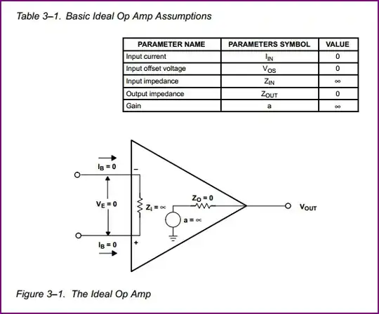
Assuming an Ideal opamp, you can make a few assumptions about it:
It has infinite gain, so any difference between the two inputs results in an infinite output (positive if the non-inverting input is higher than the inverting, negative if the opposite)
It has an infinite input impedance, meaning no current flows into it's inputs.
It has zero output impedance, meaning it can source or sink an infinite amount of current
It has an infinite bandwidth, meaning it treats any frequency identically (i.e it has infinite gain from "DC to daylight")
It has perfect characteristics in other areas such as noise, phase margin, input offset, linearity, slew rate, etc.
The above describes a theoretical component which does not exist, but makes things simple for learning purposes. These ideal characteristics make calculations easy. We can use all or some of them as we see fit, for example we may want assume the opamp has an output between two power rails (e.g. +-5V) rather than an infinite output, so (with no feedback) it will hit either rail instead on difference between inputs.
To make the Opamp useful as an amplifier (rather than a comparator if left open loop) we need to apply negative feedback. This is the brilliant idea that produces the "magical" effects which solved so many problems early amplifier designers faced before this concept was theorised by Harry Black (IIRC) and put into practice by early pioneers such as Philbrick.
Anyway, there are many books out there that discuss the properties and benefits of feedback systems (e.g. Opamps for Everyone is an excellent free book) so I'll just cover the basic gain setting and calculation procedure of two basic configurations - no-inverting and inverting.
Non-Inverting:
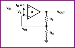
We can see the input is connected directly to the non-inverting input, so the input impedance is infinite.
The gain is defined by how much of the output is fed back to the input:
\$ \dfrac{V_{OUT}}{V_{IN}} = 1 + \dfrac{R_F}{R_G} \$
To make sense of this, it makes it easy if you remember that when used in a closed loop configuration (i.e. with feedback) the opamp will attempt to keep it's inputs equal. So lets say we input 1V at the non-inverting input, and we have an Rf of 9kΩ and Rg of 1kΩ.
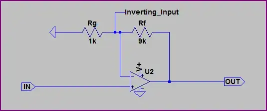
Now we know that no current flows into the input, so we can treat Rf and Rg as a simple voltage divider. So it's easy to work out the output voltage needed to produce 1V at the inverting input.
\$ 1V \cdot \dfrac{R_G + R_F}{R_G} = 1V \cdot \dfrac{10}{1} = 10V \$
So this opamp has a gain of 10.
Simulation:
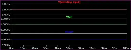
Here we can see the inverting input is the same as the input, and the output is at 10V as predicted.
Inverting:
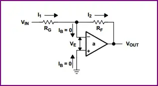
Now the inverting configuration is a bit different. The input impedance is simply Rg. Why? Because we know the inverting input is at the same voltage as the non-inverting input, and since the non-inverting input is tied to ground then we have what is known as a "virtual ground" at the inverting input.
Let's go through an example, and design for a gain of 10 again:
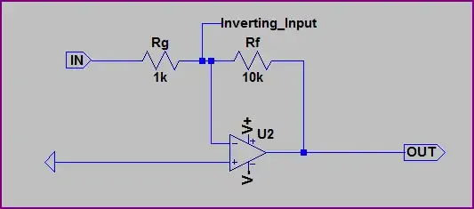
Now here we can see we have swapped the inputs round, Rf has changed to 10kΩ, and a negative rail is used. Let's do the calculations again - remembering that no current flows into the inverting input, we again have a simple voltage divider between the output and the input. However, this time the input is at 1V, and inverting input is at 0V, rather than the 1V in the previous example.
So to produce 0V at the inverting input (remember the opamp tries to keep it's inputs equal) we need a different ratio, since we have +1V at the input, and need 0V at the inverting input.
With the resistors shown, the only way to produce 0V at the inverting input is to produce an 11V difference between input and output. We know that the input impedance of Rf is 1kΩ, and the inverting input is at 0V, so there must be 1V / 1kΩ = 1mA input current. Since no current flows into the inverting input, it must flow through Rf. So the output voltage is:
\$ -1mA \cdot R_F = -1mA \cdot 10k\Omega = -10V \$
So we have a gain of -10. We can easily do a visual check to see this is correct.
Simulation:
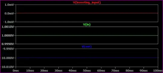
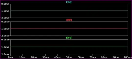
Notice the inverting input is at 0V in this example. Here are the currents thr0ugh the resistors to confirm our calculations:
Oli Glaser
- 54,990
- 3
- 76
- 147
0
Here's a simple high-level explanation of an op-amp inverting amplifier:
Basically, op-amps are amplifiers (just like what you usually want to build with an op-amp chip), except they're super high-gain inside - like 10,000x or more.
In order to use one for a simple inverting amplifier, you set up a resistor divider in-between the op-amp's output and your input signal, with the op-amp's negative input pin in the middle of the divider.
Since the op-amp's gain is so huge, some feedback magic happens and negative input pin stabilizes at the value of [output / gain], which is usually so small that you can pretend it's GND (or at least, what the op-amp thinks is GND).
As for the input current, you can pretend that the + and - pins are like the probes of a multimeter. For all intents and purposes, they don't affect the place where they're connected. They basically sense the input without drawing and current. Then the output pin supplies current which comes from the power pins.
Nicholas Clark
- 524
- 2
- 7