4

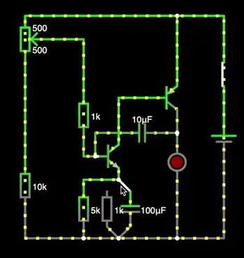
I'm trying to understand the workings of the following circuit that I've both emulated and built physically so I know it does work (I did it in a different simulator, but I've redrawn it here for your convenience - animated gifs from the simulator will follow):
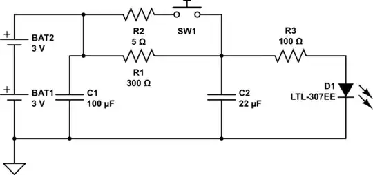
schematic

simulate this circuit – Schematic created using CircuitLab

I understand the way NPN and PNP transistor work there with the 10uF capacitor C1 draining the current away from the base of the NPN transistor until the capacitor charges, upon which the current is applied to the NPN transistor base and it allows electricity to flow through it, which in turn "opens" the PNP transistor.

What I fail to understand is what happens with the capacitor and resistor under the emitter of the NPN transistor - the current seems to drawn upwards through the 100 uF capacitor C2. The capacitor is charged through the emitter at the beginning of the simulation, so it's indeed blocking the current from going downwards from the NPN emitter, but why would it take up the current the opposite way?

This gets even more mysterious if I replace it with a diode that goes the same way - it should have almost 0 resistance so if the current was drawn upwards through the capacitor, it should also be drawn through the diode.

Specifically, what I see in the simulator:

animated gif of simulation

Now if I replace it with a diode it doesn't flow upwards at all, and I'd expect this to happen if an inversely charged capacitor causes it:

diode replacement

And if I replace it with another resistor it obviously flows downwards as expected through it:

resistor replacement

Can you explain to me what is exactly happening here?

Here is the link to this circuit made in the original circuit simulator I've been using:

Circuit in the original online simulator

ADDITION: Indeed I see now on the circuit simulation reworked by Tony Stewart EE75 that the capacitor does get in fact discharged and then charged again.

One thing that still somewhat puzzles me - on the simulator it still shows that the current is flowing from a lower voltage (grey) to higher voltage (green) through the capacitor, which is normally not the case - even next to it we see the current flowing from high (green) voltage to low (grey). Is this a glitch of the simulator rendering the colours or something? Here's what I'm referring to (animated GIF from Tony Stewart EE75's circuit):
counterintuitive flow

ElecCur
  • 43
  • 3
  • 1
    The current through the capacitor should not flow indefinitely in one direction. It should flow one way, and then the other. It is weird that Falstad shows the current through _both_ capacitors in one direction only. – Math Keeps Me Busy Oct 17 '21 at 14:30
  • You do not see the charging current in the animation because the charging current (emitter current) is a very short pulse of current that you can only see on the oscilloscope (the yellow spikes). – G36 Oct 17 '21 at 14:53
  • *"opens" the PNP transistor* - we don't use hydraulic valve terminology in electronics because it becomes confusing when we talk about open-circuits. Try the terminology "activate" or deactivate" if that helps. – Andy aka Oct 17 '21 at 14:56
  • And why do you expect to see a current flowing through a diode? You connected the diode with an anode to GND. So, to turn on the diode the voltage at the emitter needs to be negative. Wich is not the case here. – G36 Oct 17 '21 at 15:01
  • +1 for the creative use of Falstad's simulator and animated GIF saving to this site. All transistors invert voltage from base to collector so feedback thru 2 inverters with 10uF make it oscillate while the NPN emitter limits the current somewhat, maybe not enough for the LED without another R in series as the PNP saturates as a switch, momentarily. – Tony Stewart EE75 Oct 17 '21 at 15:04
  • 1
    Animated gifs are pretty useless for digging into the details. The last 5 words of the previous sentence were added just for the hobbyists amongst you not to feel too downtrodden. – Andy aka Oct 17 '21 at 15:05
  • Whoever designed this circuit needs to understand that the LED will burn out from the switched current impulses – Tony Stewart EE75 Oct 17 '21 at 15:56
  • The circuit is coming from educational material, unfortunately it's provided without much commentary except "this is how it's done" ("it" being blinking a LED), which is OK if one wants to blink a LED, but not that useful from the perspective of actually understanding what's exactly happening in the circuit. – ElecCur Oct 18 '21 at 00:32
  • Placing a resistor on series with the LED will extend the discharge period and give a better visual indication of the current flow. – Russell McMahon Oct 18 '21 at 23:02

1 Answers1

-1

There is a lot to say about each component changes I made to improve this design. But Rather than explain how your circuit works and why it overstresses an LED and why the frequency control of the pot is suboptimal, allow me to show a better solution with slight changes in values to reduce base drive currents and LED output powers from 10W pulses to 50 mW pulses suitable for small LED's .

Generally LEDs are not made for high current pulses ( e.g. typically <2x the DC rated , because the gold wire bond to Anode in LEDs with lens to be less visible and with excess current pulses becomes a fuse.

But the fundamentals are in the diode clamp position, just a linear current amplifier but lacking the necessary current limiting resistor values on the base or better on the LED to limit the current drive .

The right side switch position is your fundamental BJT Relaxation Oscillator except using a PNP instead of an NPN with diodes for positive feedback thru two inverting transistors NPN+PNP.

It is better you ask questions on the purpose of each part in doubt.

Tony Stewart EE75
  • 1
  • 3
  • 54
  • 182
  • You don't even need the emitter diode. You can feel free to change any R or C value to see the effect of the duty cycle of this slow Beacon pulse generator or make it more sinusoidal oscillation by R and C ratios. Now the Pot lowers the DC bias current to the right and slows the pulses to every 10 seconds or 1 second on the left. https://tinyurl.com/yjbkb2oj – Tony Stewart EE75 Oct 17 '21 at 16:18
  • Another variation https://tinyurl.com/yjv9rvlx Where the Pot goes from full ON to OFF with a variable duty cycle and freq. < 1 Pulse / s – Tony Stewart EE75 Oct 17 '21 at 19:26
  • Thank you, your reworked circuit indeed has shown me that the capacitor does get charged/discharged (in the original one it seemed as if it's allowing the current to flow through it continuously, which seemed very weird). – ElecCur Oct 18 '21 at 00:34
  • I've added a supplementary question in the text (since I couldn't add a gif in the comment): I'm still a bit puzzled as to why does the simulator show the voltages (high - green, low - grey) unchanged during the discharge of the capacitor...? Is this a glitch in the simulator itself? – ElecCur Oct 18 '21 at 00:53
  • its not a glitch. Feedback dumps a pulse into base-emitter cap which then decays into resistor. See bottom trace of voltage and current from emitter and current circulates to R with decayed voltage. and current spike. What is you Gif capture tool? – Tony Stewart EE75 Oct 18 '21 at 01:10
  • So that happens despite the general voltage balance? As for the GIF capture tool, I use Parallels Toolbox tools on a Mac - "Record Area" tool to make the MOV video file out of an on-screen animation and then "Make GIF" tool to make a GIF of a fragment of that MOV video file. – ElecCur Oct 18 '21 at 22:47
  • Both parts share the same voltage but after an emitter impulse current, with a voltage step rise then the current goes out into the R as the voltage ramps down – Tony Stewart EE75 Oct 19 '21 at 01:10
  • Note emitter dots and plot to the right https://tinyurl.com/yz24d3ke – Tony Stewart EE75 Oct 19 '21 at 13:20