3

Q: Using Op-Amp uA741, design an amplifier that offers a passband gain of 40dB with a minimum bandwidth of 20kHz. The current through any resistor in the amplifier should not exceed 10 mA. Include the details of the design process.

I do not understand this question. How does one solve for the maximum achievable gain by using a single uA741 op-amp? I have the unity-gain bandwidth to be 1 MHz.

ocrdu
  • 8,705
  • 21
  • 30
  • 42
  • Looks like you can use any number of resistors in your design. Any number of DC power sources to power the uA741 could be used as well (you don't have to design these). A battery of any voltage would be an example DC power source. Although the design spec can be met with only the components mentioned, you might include any number of capacitors too - since the word *passband* appears in the spec. Can you translate **40 dB gain** into a ratio of amplifier **Vout/Vin**? – glen_geek Oct 15 '21 at 16:59
  • What does the unity-gain bandwidth tell you about the bandwidth at a gain of 40dB? – TimWescott Oct 15 '21 at 18:16
  • The unity-gain bandwidth shows that I should have a bandwidth of 10kHz with a Vout/Vin gain of 100. But the problem states that I need to have a minimum bandwidth of 20kHz. How do I increase my bandwidth while keeping the 40dB gain? – IrrationalPi Oct 16 '21 at 23:47
  • 1
    Why are you using an antique 741 opamp that was introduced 54 years ago? Use a modern opamp instead. – Audioguru Aug 06 '22 at 18:00
  • 3
    @Audioguru for some bizarre, reason, these horrible antiquated parts are still apparently seen by some educators as a default/standard. Even worse, companies are selling them to naïve "makers" for use in projects. It's baffling. – Ian Bland Aug 06 '22 at 23:07
  • Some teachers still teach about the antique 741 opamp because they do not know about newer and better opamps. – Audioguru Aug 08 '22 at 01:30

4 Answers4

3

Without giving away too much of the answer, the (poorly-worded) question implies that an external amplifier circuit will have to be added to the 741 circuit for a combined overall gain of 40 dB at 20 kHz.

Across the decades and among many manufacturers, there are lotsa variations of the 741. I have 5 different datasheets, with gain-bandwidth values varying from unmentioned, to a minimum of 437 kHz, to a "typical" of 1.5 MHz. Since the performance grade of the 741 is not stated in the question, I recommend using 500 kHz for the GBW value, and stating this assumption clearly as part of the answer.

There is something to consider that probably is beyond the scope of this question, and probably the scope of the course. I'm not trying to clutter your question with real-world design tradeoffs.

But ...

IRL a linear amplifier opamp circuit never should operate right at its gain-bandwidth limit. A good rule of thumb is that the device should have at least 20 dB of headroom at the highest signal frequency of interest. That is, it should have 20dB more gain then necessary. This assures that the feedback loop is closed firmly. Every extra dB of unused gain drives down both the output impedance and signal distortion. If the circuit is running right at the gain-bandwidth edge (per the datasheet), and something drifts with temperature and the loop opens up, both the output impedance and output distortion will shoot up. Not good.

AnalogKid
  • 16,865
  • 1
  • 13
  • 25
2

The question does not imply that only one op amp should be used. And in fact, it's not really possible to reliably do it with just a single op-amp. Two of them in series, each with 20dB gain, will do the job, with enough bandwidth left to allow part-to-part variations, etc.

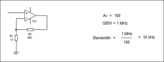
I have the unity-gain bandwidth to be 1 MHz.

That's also the so-called GBW - Gain BandWidth product. So, divide 1MHz by gain (in linear, not log units), and you get the bandwidth.

An op-amp with 1MHz GBW has 10kHz of bandwidth at gain of 100 (=40dB). Since you need 20kHz of bandwidth, a single op-amp will not be enough.

The current through any resistor in the amplifier should not exceed 10 mA.

That's good advice, since a 741 will have real trouble driving that much current out the output while maintaining large-signal gain, never mind distortion.

The circuit below would do the trick, as long as the signal source can deal with 5kohm load impedance of the 1st stage.
schematic

simulate this circuit – Schematic created using CircuitLab

The feedback resistors on the 2nd stage are scaled by the gain of the 1st stage. That way, both stages' outputs drive the same current through the feedback network.

This circuit of course would also work with two non-inverting stages.

Ideally, though, given how poorly a 741 performs at the top end of the audio frequency range, I'd suggest splitting this gain across three stages, not two. This would give distortion about as low as one can get from those parts.

2

Title

Amplifier

It is possible to increase BW by adding more stages. For op amps with a GBW of 1 MHz, replacing one stage which has a gain of 100 with two cascaded stages each having a gain of 10 increases the bandwidth from 10 kHz to 64 kHz. Bandwidth increases by a factor of 6.4

Amplifier

Adding a third amplifier and setting each of the three amplifiers' gains to 4.7 to gives an overall gain of 100 and an overall bandwidth of about 109 kHz.

Amplifier

So by cascading three amplifiers, bandwidth increases by a factor of about 1.7 times the bandwidth of just the two amplifiers.

The bandwidths come about because the overall bandwidths of the cascaded amplifiers are measured at the overall -3 dB frequency and so the gain reduction of each cascaded amplifier will be less than -3 dB. For example, for two cascaded amplifiers, each amplifier will have a -1.5dB drop at the cut-off frequency. For three cascaded amplifiers, each amplifier will have a -1 dB drop at the cut-off frequency.

1

You assume the gain-bandwidth product is \$10^6\$.

So you can have a gain of 1000 but the bandwidth will be 1kHz.

Spehro Pefhany
  • 376,485
  • 21
  • 320
  • 842