simulate this circuit – Schematic created using CircuitLab
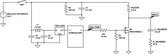
The circuit above is used to control a 240W ceramic heater by means of a PWM signal, generated by a microcontroller, with 5V logic. The input is a standard 280W AC-DC external power adapter, the Meanwell GST280A24.The C1 is a large electrolytic capacitor, 2200 uF, with 35V maximum voltage, placed close to the load. This capacitor has a maximum ripple current of 2,06A @ 100 KHz. We can noticed a low but clear humming sound when the circuit is switched on. The sound is coming from both the C1 and the snubber capacitor. We measured the frequency of the acoustic noise and it is around 1.200 Hz. We do not clearly understand what it is happening. The load should be drawing pulsed current at 10A, and there is no inductor in series with the 24V line to help with the current requirements. Could this be the problem? The voltage signal measured in the MEAS node is very clean, there are no spikes or other strange behaviour. Could this be the sign of the C1 suffering because of the exceeding limits of the ripple current? Or would that not be a problem at 30 Hz? Should we skip the C1 completely if reliability over time is a requirement? We do not have physical space on the control card for inserting large inductor coils and several large capacitors, thus the filter on the power input line should be kept at a bare minimum.