The battery charger chip seems to be On Semi MC33342 (chip is labeled 33342). This is a NiCd/NiMH "smart charger" chip, which means if you feed it power in the right input range it will handle battery charging, controlling the big power transistor on the yellow circuit board. In brief, it looks at voltage and temperature of the battery and turns the power transistor on or off to charge or stop charging the battery. It uses "negative slope voltage detection" charge termination, where during charging the battery voltage will rise until it's almost full, then start going downwards. Where the voltage goes from upwards to downwards (looks like the peak of a hill if you graphed voltage during charging) is where fast charge ends. The current into the battery must be limited somehow, so there will be some control on the power transistor to limit the current through it, either inside the package or external to it. I haven't tried to trace out the schematic from the circuit board but you may try to figure it out yourself from the example schematic in the data sheet.
http://www.onsemi.com/pub_link/Collateral/MC33340-D.PDF
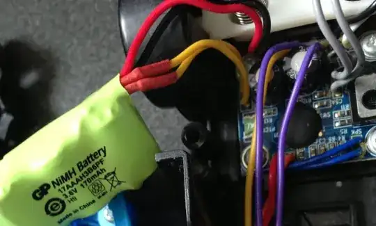
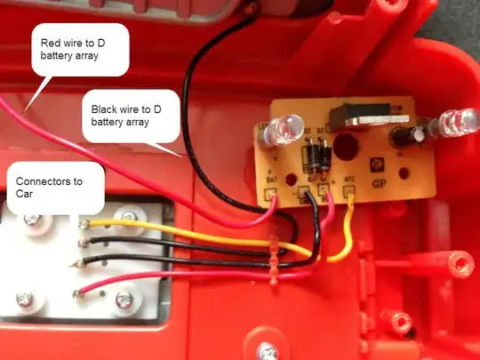
The yellow wires are for a negative-temperature-coefficient thermistor (labeled NTC on the yellow circuit board), probably a 10kohm resistor that varies resistance with temperature, a lower resistance the warmer it gets. The chip uses this to see if the battery temperature is rising too quickly or above/below a safety threshold. Technically you can replace this with a plain resistor and the circuit will still mostly work, it'll just be blind to the battery temperature (will always think it's ok), which is unsafe and so a bad idea. NiMH can get very hot if fast charging is not stopped when they're full, hot enough to burn your hand.
Because there's a proper regulated battery charger between the 4 x D cells and the NiMH battery, it would almost certainly work if you just put a 6V DC source with sufficient current capability at the +/- leads of the DC battery compartment, or associated wires. Because the NiMH battery is so small, 6V 500mA may be more than enough. Check the actual current draw from the D cells when the NiMH is almost full to get a more accurate picture, then overspecify by 2x or more and it will probably be ok. Also note that 4 x D cells are not going to be 6V all the time, they will be closer to 4V when almost dead, so it's very likely that a 5V 500mA regulated source will also work, for example a cell phone USB wall adapter if you have an extra one. An in-line fuse would be a good idea. Depending on how the circuit board is designed it may be able to take an input voltage quite a bit higher than 6V; the chip specifies 18V max but you'd have to understand the rest of the circuit also. It may be possible to use a 12V rechargeable lead-acid motorcycle battery instead of the D cells if you need to recharge away from a wall outlet, but beware that trying it may or may not fry the charger circuit depending on how it was designed.
As to swapping out for a bigger battery pack, this is probably possible, as the smart charger chip can handle a variety of cell configurations, but you may have to alter the charger circuit so it knows to run a higher current into the battery pack, or set a longer timeout period, etc. This may require soldering tiny resistors (changing their values) which you may not have on hand. It is not recommended to increase charge current (decrease charge time) on the pack you've already got as 40 minutes is already a pretty fast charge time. There may be NiMH out there that can charge in 15 minutes but if you had such a battery they would have designed the charger to take advantage of it. Anything under 1 hour charge is already "fast charge" and charging it faster may severely shorten the life of the pack, or worse, create safety issues. If you do try a different battery pack you'd want to keep the same cell configuration, which appears to be 3 cells in series. Also cut the NTC thermistor loose from the small pack and attach it to the new pack with thermally conductive adhesive, or possibly buy another one if you can figure out which one it is.
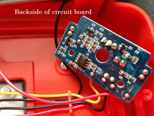
The proper way to change the battery pack to a larger one would be to reverse-engineer the circuit board so you have a schematic you can compare with the reference schematic in the chip data sheet. Try to understand the circuit fully before you modify it. It'd help if you post another photo showing what's printed on the face of the big power transistor on the yellow side of the charger board.
The battery pack seems to connect to the inside of the car, and the wires pass through somehow to different wires before going to the battery charger board. You'd want to disconnect the battery from the car and wire it directly to the charger board before testing any modified charger/battery design so you don't blow up your car, then wire it back when it works. If the wires only pass through then it should be easy, if something in the car circuit board modifies the power path then you'd want to understand that as well.