Before I had a formal education in electronics, my understanding of transistors was really sketchy. When I started courses it was immediately clear why I couldn't grok them properly - I didn't know about current and voltage.
I mean, I knew what they were, and I knew Ohm's law, but I didn't have a good enough understanding of how currents and voltage add and subtract, what happens at branches, or how they were all related in a bigger picture sense. I thought current got slowed down at each resistor. I thought current couldn't flow through a capacitor. I thought a bunch of things that were just plain wrong, because I read them in books for beginners or magazines, or got taught by people who didn't really understand either.
Everything I had read was really explanations for 10-year-olds, and completely innapropriate for anything more complex than an LED, resistor and transistor setup.
My problem, it turned out, was never with transistors, it was with Kirchhoff's Voltage Law, Kirchhoff's current law, and my fundamental understanding of what a voltage source is, and what a current source is. Terms like "sinking" and "sourcing" current were missing from my vocabulary. Lots of little things were missing.
Transistors are hard, it's true, but they are impossible to understand without a really solid foundation to place them on in your mind. In my case I had to unlearn a lot of crap, and luckily I had university to re-educate me. These days there's the Internet, but I imagine it's hard for a beginner to identify the crap from the gold in all those Youtube videos. Some of them make me cringe.
Anyway, there are thousands upon thousands of "exercises" out there, and you should do as many as possible. Every day you'll find something that either fills a gap in your understanding, or highlights some misconception you aready have. Believe me, even today I still have "aha" moments about stuff I thought I had figured out 20 years ago.
Let me highlight some issues that I (and my students) have had to address. They might not apply to you, but they might help.
Vernacular
All students of mine use terms that highlight problems with their understanding. Perhaps you can identify your own problems by trying to find out why certain terms are used.
When a student says to me "the voltage through this resistor" I immediately know they haven't understood what voltage is. Voltage doesn't flow through things, voltage exists at places, or more precisely voltage difference appears between places. I do not use the word "appears" for no reason, it implies something.
When they say "the current gets to this resistor and ...", I can be almost certain they've misunderstood the nature of current. In a long chain of components, the current is same everywhere along that chain, independent of the order of the components, or their number, or time. Voltage and current are established instantaneously everywhere in a circuit, and are a function of everything in the circuit, all at once. This becomes clear when you start solving the simultaneous equations from Kirchhoff's and Ohm's laws. They are called simultaneous for a reason.
"At" and "across", are terms used to refer to voltage only. As I already stated, only voltage differences exist, between two points, and absolute voltages do not exist. Therefore, when someone says "the voltage at point X is 15V", what they really mean is "the voltage between point X and some point I've arbitrarily declared to be 0V (ground), is 15V."
Laws
Learn your basics really really well, and the transistors will fit in just fine. As I said, do exercises, and in particular look for these terms:
- Kirchhoff's Current Law
- Kirchhoff's Voltage Law
- Ohm's law and the Power Law
- Thevenin (and perhaps Norton) Equivalents
Potential dividers
95% of circuits rely on potential dividers (a.k.a. resistor dividers, or voltage dividers). Learn to spot them, because they are everywhere. Understand what happens to all the current as you increase this resistance here, that current there, tweak this voltage here and so on. Understand them in terms of the current through the components, the voltage across each component.
Develop an intuition for their behaviour, until you no longer have to think about it. Whenever you see two or more resistors in series, think "potential divider" and can instantly see how the total voltage is shared across each, to the point where you can estimate the voltages just by glancing at the resistance values. It's not as hard as you think.
Even a transistor can be a member of a potential divider, and it has to obey the same rules as every other member. If it becomes "more resistive", the voltage across it and current through it will do the same as a resistor would in its place. If you understand what resistors in a potential divider do, and how the voltages and current change when an indiviual resistance changes, then replacing one with a transistor is not such a leap of understanding.
Here are a few examples, of potential dividers, some using only resistors, but some using a mix of components. Below them I'll write some comments about my instantaneous thoughts when I see them:
simulate this circuit – Schematic created using CircuitLab
The resistances are identical, passing the same current, dropping the same voltage. Therefore the voltage at X is half way between the top and bottom voltages, so \$V_X = 6V\$.
100Ω is very small compared to the two 10kΩ resistors, and so the voltage it develops will be very close to zero. The voltage at Y must be near zero. The remaining majority of 12V must be divided equally between the other two resistors, at slightly under 6V each. Therefore the potential at X must be slightly over 6V.
The two resistors have the same value, sharing the same voltage across them, as for (1) above. X must be half way between the top and bottom voltages, +24V and -24V respectively, which is zero volts. \$V_X = 0V\$.
The LED chooses its voltage, which will be about 2V for a green model. \$V_X \approx 2V \$, irrespective of the value of R8. The remaining 3V must be across R8. By Ohm's law I estimate current through R8 and D1 to be about 10mA (3V ÷ 330Ω)
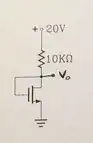
The transistor Q1 is off. That means the effective resistance between its collector and emitter is very very high compared to R9, so most of the 5V source is dropped across Q1. The voltage dropped across R9 is practically zero, and the voltage at X must be 5V.
The top transistor Q2 is off, so its drain-to-source resistance is very high. The bottom transistor Q3 is on (saturated), so its collector-to-emitter resistance is very low. Most of the 12V source is therefore dropped across the highest effective resistance, Q2, with almost 0V remaining across Q3. \$V_X = 0V\$
I made every one of my students do exercises like this, to describe qualitatively, and without algebra, the behaviour of divider configurations like this. It's important to be able to take an educated guess at the distribution of voltages, without resorting to arithmetic and algebra every time. You absolutely need to develop an intuitive feel for this behaviour.
Redraw the circuit
Often it's just not possible to understand a circuit because it's been drawn in a way that doesn't suit your mental model of direction of current flow, or potential "steps". In my mind, and I think in the minds of most engineers, current flows from high potential to low, in the same way that water flows downwards from high gravitational potential to low. It makes sense to draw circuits with high potentials at the top, and low potentials at the bottom. That way potentials drops as you move down the circuit, and current flows from top to bottom. Do this just to facilitate the mental gymnastics that go on when trying to analyse the circuit.
Do the same with signal directions. Left to right, just like writing. Inputs arrive from the left, outputs leave to the right.
Obviously this is not always possible. There may be feedback signals going to the left, and sometimes you don't know which potential is higher, but you can always simplify your mental processes by trying to stick with these conventions. It will also help when communicating with other engineers.
Here are two representations of the exact same circuit, the first is a mess, the second is easier to analyse:
simulate this circuit
I want to draw your attention to the resistive potential divider outlined in the orange box. It's positioned between the opamp output and ground, and is dividing the opamp's output potential by about 3. Learn to spot these "modular" elements.
Here's an example of a circuit which makes my eyes hurt, and which illustrates the importance of this:

simulate this circuit
In the left version I have to turn my mind upside down to see what's going on. When you ask me "what's the voltage at X?", I can't immediately tell you.
If you show me the circuit on the right, and ask the same question, I immediately know that at Y the potential is 6V,and at X it must be 1.7V less than that, at 4.3V, due to the drop of 1.7V across a typical red LED. And yet the two circuits are identical.
Apologies if any (or all) of that was already obvious to you, but I do hope it helps to build some skills ready for the transistors to come. These ideas have helped me (and my students) a lot over the years.