0
V=IZg 
V=IaZ
IaZ=IZg
LdIc/dt+RIc=(L+Lg)di/dt+(R+Rg)i

schematic

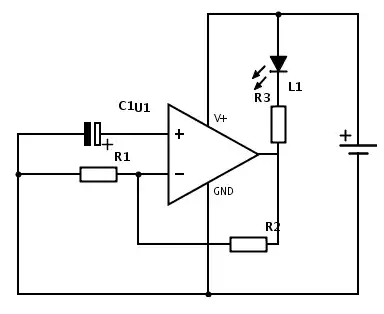
simulate this circuit – Schematic created using CircuitLab

Hi ,

how can I get state space model in the form of dx/dt=Ax+Bu?

Ic is input and I is the state variable. I am getting derivative of Ic as input. How can I eliminate that?

safi2016
  • 21
  • 2
  • Is this a duplicate of https://electronics.stackexchange.com/questions/588904/finding-state-space-equation-in-x-axbu-form ? – AJN Oct 08 '21 at 02:27
  • Are you familiar with Laplace transform ? Have you done any steady state analysis for such circuits ? If so, you might have seen the replacement \$\frac{d}{dt} (\cdot) \leftrightarrow \omega \times (\cdot)\$ or \$\frac{d}{dt} (\cdot) \leftrightarrow s \times (\cdot)\$. – AJN Oct 08 '21 at 12:34
  • Yes I know the replacement. But I want to do it in d/dt format and that is causing the issue. – safi2016 Oct 08 '21 at 13:37
  • @AJN do you know the equivalent circuit of grid tied current source inverter in dq reference frame. That's what I am trying to do. – safi2016 Oct 08 '21 at 13:40
  • **1** The system may be setup in such a way that when represented as a transfer function, it is not a proper transfer function; i.e, the degree of the numerator is not strictly smaller than the denominator. **2** That would indicate that your system representation `(A,B,C,D)` would have a non zero `D` matrix. You have not mentioned anything about the output equation `Y=CX+DU` in the question. Ignoring this may be what is preventing you from being able to represent the system as `dX = AX+BU; Y=CX+DU`. – AJN Oct 08 '21 at 14:55
  • **3** Your question has too few details. please add info inside the above comments into directly into the question. **a)** that you want to do in the d/dt representation (and the reason for that) and **b)** the _actual_ problem i.e. grid-tied current source inverter. – AJN Oct 08 '21 at 14:56
  • This circuit might **not** have a state space form. The output equation is (by [current division formula](https://en.wikipedia.org/wiki/Current_divider)) \$Y = \mathbf{0} X + D U\$ where \$U = I_c\$ and \$D = \frac{R_1+sL_1}{R_1+sL_1 + R_2 + sL_2}\$. – AJN Oct 08 '21 at 15:04

1 Answers1

1

This circuit might not have a state space form (the way it is drawn and defined now).

The output equation is (by current division formula) \$Y = \mathbf{0} X + D U\$ where \$U = I_c\$ and $$D = \frac{R_1+sL_1}{R_1+sL_1 + R_2 + sL_2}$$

Since the output is fully defined by the feed-through matrix \$D\$ and the input \$U\$, the state vector \$X\$ and the matrices \$A,B\$ can be left undefined.

A state space formulation might make sense only if the input and/or the output was defined differently or if the circuit was drawn differently.

AJN
  • 3,756
  • 1
  • 9
  • 20
  • Thanks for your help. I am trying to solve equivalent circuit of grid connected current source inverter in dq reference frame which looks like this I guess https://electronics.stackexchange.com/questions/588904/finding-state-space-equation-in-x-axbu-form. Is this the correct representation? if so, then how can I solve that ? – safi2016 Oct 09 '21 at 00:13