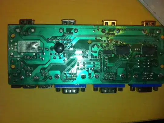
I designed a relay network board. The idea is to select one differential measurement points from a high voltage device. In order to do that, I used these solid state relays.
You will see the board below:
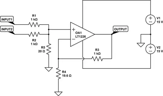
The board has two differential probes actually. I got the schematics from this address. And I've seen that this is pretty basic in differential probes but I will give the block below for your reviews. The block is working fine doing its job.
What I did in this board is to connect the probes inputs to 8 relays for positive measurement point selection and 8 relays for negative measurement point selection.
In the datasheets of the relays, it states the input to output cap is 1 pF.
So, when one channel is being measured, and there is a sine wave on as input, the other with square wave is not measured and its relay is open. This square wave interferes the measurement via this cap and distorts the output. I made the simulation:
And measured the same case and verified:
My question is, what can I do about it? Is there a solution to prevent this capacitive effect on the relays?
Before you suggest to say use different amplifiers for each, I have to say this will become a product and needs to be cost effective and reliable. Before you say 'Why not convert it to single end?' I have to use differential output because the receiving end is a fixed differential input digitizer.
