2

Please refer to post PWM generator circuit review for initial simulation and bugs on the circuit.

In general, the circuit works very well and I can control a 12V fan with the PWM output of the 555 which is varied according to the potentiometer. However, I am experiencing the following issue:

After around 1-2 months of constant use, it is like the gremlins come overnight and change the timing circuit... The selected frequency of 25 kHz for when the duty cycle is 50% shifts to a higher frequency...

The passive components aren't getting degraded. I know this because as soon as I replace the 555 with a new one, the frequency goes back to 25 kHz.

Here is a photo of the broken circuit output after 1-2 months of constant use: enter image description here
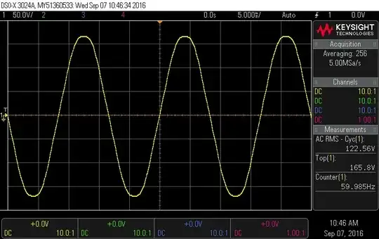
As you can see, the frequency at 50% duty cycle is 32 kHz

This is now the SAME PCB but with the 555 swapped for a new one: enter image description here
Now, the frequency is back to the required 25 kHz.

I chose a NE555D from Texas Instruments instead of a cheap Chinese one precisely to avoid stuff like this happening but it did not do the trick apparently.

The circuit is connected to a 12V/1A "wall-wart" power supply and a 12V fan. There are no extreme low/high temperatures and no ESD events as far as I am aware as the pot has a plastic dial inserted.

Does anybody know what could be happening that damages the 555 after a prolonged used time?

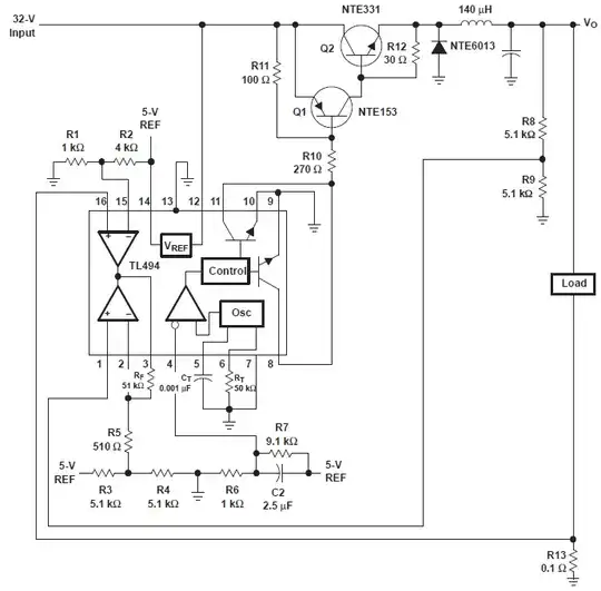
Here is the full circuit for reference (R5 is DNP), previous oscilloscope shots are from probing pin 1 in J2. enter image description here
enter image description here

Thank you

Update 07/10/2021

I tried soldering back again the "broken" 555 using solvent and a toothbrush to clean the PCB. Initially, it looked like it worked, and I even reswapped to make sure this is correct. Then, everything started to lose coherence. I saw with my own eyes on the oscilloscope how both the duty cycle and frequency started to slowly drift but this time to lower frequency instead of higher to the point that the fan turned off. I think using the heat gun a few times on the IC made me damage the parts... I am now testing a board with a 10K pot and 3.3nF cap to see how it behaves.

The big issue here is that I don't exactly know what is happening and this problem only manifested after 2 months of use. Because I thought the circuit was good, I already manufactured 2700 of these PCBs for my product.

The challenge now is to take the right course of action:

  1. Do nothing and hope it was just environmental and assembly conditions such as dust and excess flux
  2. Change the RC network to a lower resistance value and higher cap. This will involve buying new components and paying the factory for the rework
  3. Same as 2 but change the 555 for a TLC555 as these are more precise and deal better with smaller capacitances. Components are more expensive than option 2 but rework should be cheaper
  4. Use an MCU instead such as the ATtiny202... Most expensive option as I will need to get a new PCB and buy components, also the price per unit will be higher to not mention supply issues with the part...

#hwentreperneur

RWeiser
  • 131
  • 1
  • 8
  • The timing capacitor is really 100 pF? Which material is it, NP0/C0G, something else? How is your PCB layout? – Justme Oct 06 '21 at 10:31
  • 82pF to be exact... yes, NP0 82pF ±5% 50V 0603. I'll upload the PCB layout – RWeiser Oct 06 '21 at 10:45
  • 3
    What happens if you put the original 555 back in the circuit? Could be flux contamination. As soon as you heat it up, problem gone? Clean the pcb thoroughly. Why aren’t you using a cmos 555 part? – Kartman Oct 06 '21 at 10:52
  • I am using this component https://www.ti.com/lit/ds/symlink/ne555.pdf Can you link me to a CMOS 555? Why should I use a CMOS 555? I'll try to solder it back and let you know what happens. – RWeiser Oct 06 '21 at 11:01
  • CMOS parts include TLC555, 7555, LMC555, and others. – Jasen Слава Україні Oct 06 '21 at 11:17
  • the CMOS parts use a P-FET for the top transistor on the out pin this gets a higher voltage on that pin that the bipolar 555 can manage (because it uses an NPN) – Jasen Слава Україні Oct 06 '21 at 11:22
  • The output is driving an NPN, so I don't think that rail-to-rail out put matters... however, it seems that the TLC555 is recommended for "precision circuits" and seems overall more reliable? – RWeiser Oct 06 '21 at 11:37
  • the output is ultimately driving the timing capacitor, so having rail-to-rail output reduces supply sensitivity – Jasen Слава Україні Oct 06 '21 at 12:14
  • The flux contamination idea comes closest, I think. Are you sure you are using proper **electronic grade** solder (and flux, if you used liquid flux)? Acid flux will cause problems like this. – Spehro Pefhany Oct 06 '21 at 14:05
  • My guess is that with such low capacitance, you can have variations due to environmental conditions. Also, potentiometers are notorious for issues due to oxidation/dust. I would recommend going with a higher value capacitor and lower resistance. Unless you absolutely have to have that potentiometer, I'd replace it with the closest values of resistors that give you the duty cycle you need. Also, make sure that the circuit is either grounded well or completely isolated electrically from the world. Let us know in 2 months !! – kalyanswaroop Oct 06 '21 at 15:02
  • Do you have a few spare timers and at least one spare PCB? Place timers in your circuit one by one and make a table of output frequencies. Repeat with the spare board. You need to identify if it is a circuit design problem, component problem, PCB problem, supply problem or a part problem. I doubt it very much that it is a part problem. – Syed Oct 06 '21 at 15:27
  • 82pF is small compared to PCB parasitics (including flux, dust, charge buildup, humidity, etc). I'd look at increasing it by 10-100x and adjust to a smaller resistor (multi-turn style if you can). – Aaron Oct 06 '21 at 19:30
  • Have you tried just powering it down, clean it with rubbing alcohol then try it again to see if it returns to normal operation? – Aaron Oct 06 '21 at 19:32
  • Post updated... – RWeiser Oct 07 '21 at 07:17
  • I'd check the potentiometer, it's the component most prone to drifting; try putting a fixed resistor instead (at least in the beginning) – Lorenzo Marcantonio Oct 07 '21 at 08:34

0 Answers0