What you are embarking upon is a big, big topic. However, there are a few basic principles about "closing the loop" that are simple enough to understand. You should start by understanding why we close the loop.
The principle described in plain English is this: you have something that isn't very accurate. You tell it what you want, and it does a poor job of actually giving it to you. It tries, but for whatever reason fails. Perhaps it produces something that is always more than you asked for, something you might call an undesired "offset". Perhaps it provides double what you asked for. Even worse, it doesn't make those mistakes in a predictable way, so you can't even compensate for the errors after the fact.
What you need is a way of measuring whats coming out of your device, comparing it with what you want to come out of it, and making adjustments to the input of the device to bring about a change in output which matches what you asked for.
This is called feedback, in particular, "negative" feedback. A system with feedback is called a "closed loop". By implementing feedback, your are "closing the loop". It's easy to understand negative feedback with an analogy. When driving a car, the road meanders, and you are able to follow it quite precisely by steering, but you have to see the road ahead, and adjust the position of the steering wheel accordingly.
There is negative feedback in effect here. You know where you want to go, this value being the required output. You know where you are going, and the difference between this value and the required value is called the "error". If the error is such that you are going too far to the right, you steer in the direction opposite to the error, to the left. If where you are currently going is to the left of your required direction, you steer right instead. The key point here is that you always steer in a direction opposite to the error, in an attempt to reduce the error to zero, hence my use of the word "negative".
An interesting property of negative feedback is that you don't actually need to know exactly how far, how many degrees, to turn the steering wheel. You simply turn it in the correct direction to reduce the error. Sure, if you are way off course, you steer more sharply, and for small errors your steering inputs are more gentle, but at no point do you ever consider the exact amount of rotation of the steering wheel, only its direction.
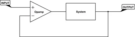
All closed loop control systems like this have the same basic structure:
simulate this circuit – Schematic created using CircuitLab
There are two elements here that I didn't describe above. The first is ×A. It's simply a very high gain amplifier, whose purpose is to apply a much greater version of the error to the input of your system, to improve reponse time (among other things).
The second unit ×ß is simply muliplying the output by some factor ß. The effect this has is that you may control the gain of the overall system, the "closed loop gain". For instance if you only feed back half of the current output, the error is one half of what it usually would be, and the output must swing twice as far in order to bring the error down to zero, to achieve equilibrium. Thus if \$\beta = \frac{1}{2}\$, then closed loop gain is 2, and the output will be 2 times the input.
Many system don't need gain, and require only that the output settle at a value equal to the input. For that you need \$\beta = 1\$, for a closed loop gain of 1. The whole thing reduces to this:
simulate this circuit
It's possible for the A and ß elements to introduce problems of their own, in the form of phase shifts. These would be akin to driving blind while someone gives you instructions to steer, but always 2 seconds too late, or too early. You can see why that would be a problem. In electronics terms, it's possible at certain frequencies of input, the that combination of A and ß can invert the signal, creating feedback which is positive. That's like turning the steering wheel in the wrong direction, increasing the error instead. Crash.
The maths of this is way beyond the scope of this answer, but just be aware of the potential for problems due to phase shift. See Barkhausen stability criterion, and Frequency compensation.
The component we usually use in closed loops like this is the operational amplifier, or "opamp", which combines the difference calcuation and the multiplication (amplification) by A into a single unit. Using an opamp, the circuit looks like this:
simulate this circuit
Just to drive home the concept of controlling gain by choosing values for ß, take a look at these two circuits, which should already be familiar. They are a voltage follower and a non-inverting amplifier using opamps:
simulate this circuit
There's no "system" in there, but closed loop principles still apply. For the follower, \$V_{OUT1} = V_{IN1}\$ because \$\beta=1\$, and for the non-inverting amplifier, \$V_{OUT2} = 2 \times V_{IN2}\$ because \$\beta=\frac{1}{2}\$, just as I described.
Beginners who don't understand these principles might build a push-pull audio amplifier circuit like this:
simulate this circuit
This is supposed to be a power amplifier with a gain of +10. It's a terrible design for many reasons, the greatest of which is that the output stage will have horrendous crossover distortion, and the output can never be equal to the input due to the base-emitter voltage drop of the whichever transistor is currently active:

Both of these problems can be (mostly) solved by placing the push-pull stage inside the feedback loop of the opamp. We literally move one connection; we take negative feedback not from the opamp's own output, but from the overall output:
simulate this circuit
Now you still have your gain of ten, but the problems of distortion are immensely diminished. We moved the push-pull "system" into the feedback loop, forming a complete system exactly like the closed loop configurations at the start of this answer, and we now benefit from the linearisation and predictability afforded by closing the loop. There are still problems, as you can see, but these can be solved by properly biasing Q1 and Q2.
Now all that remains is to put all this in the context of your project.
Put your class-D amplifier in the loop, in the place of "system" in my diagrams, as I did with that push-pull stage.
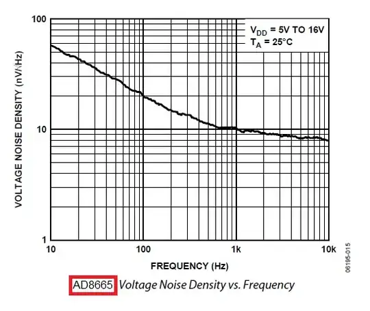
It may work, it may not, but if you do have problems, they will likely be due to phase shifts occuring somewhere in the path from opamp output back around to opamp input, for certain frequencies present in the input signal. They will almost certainly be caused by the LC filter stage, and also by any load your place (like a loudspeaker) at the output. As I said, that's a big topic in itself, and I wish you luck on this journey you've started.

