Does it looks a good schematic to do a proper 29 V to 5 V logic level conversion, any improvements or suggestions?

Asked
Active
Viewed 663 times
2
winny
- 13,064
- 6
- 46
- 63
Vaikis2006
- 33
- 3
-
What speed are we talking about? – winny Sep 30 '21 at 10:51
-
I believe baud rate will be 9600 bps, just want to decode some gate automation. – Vaikis2006 Sep 30 '21 at 12:00
-
Does the signal go negative at any time? – Spehro Pefhany Sep 30 '21 at 12:38
-
@Vaikis2006 Baud rate means a communication protocol - what is the source protocol? 29V is too high to be RS-422/485. RS-232 can go as high as +/-15V, but is never 0-29V... where is this signal coming from? – J... Oct 01 '21 at 12:06
2 Answers
7
any improvements or suggestions?
Instead of all that complication, what about two resistors forming a potential divider: -
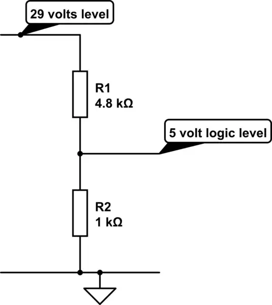
simulate this circuit – Schematic created using CircuitLab
Andy aka
- 434,556
- 28
- 351
- 777
-
hand in my lot 18K and 3.3K, which is ~4.5V and couldnt read Data.... – Vaikis2006 Sep 30 '21 at 12:04
-
Maybe there was a reason like noise on the 29 volt logic line or 4.5 volts not being enough for the receiver (unspecified) or maybe the overall higher impedance of your resistors was too much for the receiving circuit? – Andy aka Sep 30 '21 at 12:10
-
6
Andy Aka's solution of a simple potential divider is what I would do, but your circuit will work too.
R4 is redundant, you can replace it with a direct connection between collector of Q1 and base of Q2. If your next question is "but don't we need current limiting on the base?", then my answer is you already have it, in R2.
All the resistor values you have chosen are on the low side. That may help with noise, and provide better switching speeds, but it's very wasteful of power. R5 (470Ω) will pass 10mA of current when Q2 is on, when you really only need microamps. I'd make it 10kΩ.
The same goes for R2, which is providing current for Q2's base when Q1 is off. You only need a tiny current there, especially if you've increased R5 also. My choice would be more like 47kΩ, but if you've increased R5, you can make R2 hundreds of kilohms, and still switch Q2 properly.
R1 will draw nearly 30mA from that 29V input when it's high; your source may not like that. Again, a more reasonable value for R1 would be tens of kilohms.
Lastly, if you are certain that your 29V digial signal will drop below 0.7V when low, then there's no problem. If however there's a small chance of it hovering above that level, you should add a resistor between Q1's base and ground, just to help Q1 switch off.
Here are all these changes in place:
simulate this circuit – Schematic created using CircuitLab

Simon Fitch
- 27,759
- 2
- 16
- 87