I've been studying CMOS logic gate design, such as an inverter here:
Why do we need the N-channel MOSFET at the bottom at all? Couldn't it be replaced with a simple resistor into ground like this?
I've been studying CMOS logic gate design, such as an inverter here:
Why do we need the N-channel MOSFET at the bottom at all? Couldn't it be replaced with a simple resistor into ground like this?
Couldn't it be replaced with a simple resistor into ground like this?
Yes it can and is has been done:
there's also the complementary version:
We've been there and done that! So why are we almost exclusively using CMOS these days?
Think about the situation when the PMOS or NMOS (in PMOS or NMOS logic) is switched ON. Then a current flows. That current flows all the time until you switch the MOSFET off.
On average in a large design, I would expect half the transistors to be switched on and the other half to be switched of. With many transistors, that's a lot of current!
That means, a lot of power is consumed.
That means that large and complex NMOS / PMOS logic chip will get HOT.
This is solved when using CMOS logic as the resistor is replaced with another MOSFET that will be off so no current can flow. Only when you use a CMOS circuit at high speed will it consume more current. When a CMOS circuit is in a static state (does not change), it consumes almost no current (only some leakage current).
Another advantage is that a MOSFET can have a very low resistance when it is on, much lower than a resistor. OK, you can make the resistor's value lower but then what happens to the current when the MOSFET is switched on? Yes, an even larger current.
So CMOS logic is much more power efficient and can also be much faster for the same amount of power that is used.
As we can only dissipate a limited amount of power in one IC, CMOS designs can also be much more complex than NMOS or PMOS logic designs.
So why does NMOS / PMOS logic exist? At the time when these technologies were used, CMOS was not invented yet and/or the fabrication process was too expensive to make a competitive IC. Later, CMOS technology was (cost) optimized and became the standard choice of IC technology that it is today. So NMOS / PMOS logic are simply no longer needed for new designs.
In the early days of MOS (and, indeed, bipolar logic) they did exactly that: used only one type of transistor and used a pull-up or pull-down resistor built in silicon to achieve the opposite state. This was an economical way to make logic that used fewer process steps, in a time when extra process steps were very expensive (they’re still not cheap, but the advantages of complementary types justify the cost, as we’ll see below.)
What you’ve drawn in your second diagram is more or less what PMOS logic looks like. As it so happens, PMOS was the first popular MOS logic (c. 1964) on the market, until NMOS became viable once certain manufacturing issues (materials purity) specific to NMOS were solved.
What’s the matter with PMOS? PMOS transistors are inherently slower than NMOS due to their use of holes as a majority carriers vs. electrons in NMOS (electron mobility is much higher than hole mobility, by about 2.5x). PMOS also requires a larger transistor size for equivalent drive capability. So once NMOS became practical, PMOS’s days were numbered.
With the larger adoption of NMOS (c. 1971), PMOS shifted to being promoted as a low-power alternative and so continued to find use in consumer and military applications, until it was fully supplanted by NMOS. NMOS itself gave way to CMOS in the mid-1980s.
In both PMOS and NMOS, the passive ‘resistor’ is constructed from a depletion mode device, while the active FET is enhancement mode. Depletion mode FETs have a default-on threshold, so that when Vgs = 0 the device is conducting. This pull-up (or -down) depletion-mode FET also has its channel width and length adjusted so that its on resistance is about 5x of the enhancement mode FET.
So what’s the problem with that resistor? You may have noticed that the PMOS pFET inverter is sourcing current when the pFET is pulling the line high: current is flowing through the FET to the pull-down. This uses power even when the inverter isn’t doing anything. This is called static power consumption, with ‘static’ meaning ‘not changing’. NMOS has the same issue when driving out a low: the nFET is sinking current.
Compare the CMOS inverter. When outputting a logic high the pFET is on, but the nFET is off, so no current flows. Same thing when outputting a low: nFET on, pFET off, no current flow. This allows CMOS to have theoretically zero static power consumption. That’s a huge win, and worth the extra process steps to make it just by itself.
CMOS is also faster due to the use of active enhancement-mode FETs in both directions instead of a weakened depletion-mode pull-down (pull-up for NMOS.) For these two reasons and some others (like simpler biasing) CMOS is the dominant logic used today.
Nevertheless, sometimes the passive pull-up / pull-down approach is useful for solving certain problems, such as level shifting, constructing wire-OR logic or implementing shared buses like I2C.
A Mosfet always has a voltage drop associated with it. So if you want to switch within the full boundaries (V+ <-> V-) you need both channels. If you are okay with the voltage drop on your output signal (V+ - x) you are good to go. But think about cascading. This effect worsens with the number of sequential arrangements.
Every trace has some capaticance C. Resistor from your example will form lowpass filter with cut-off frequency fc=1/2PiR*C. Lower R gives highier cut-off frequency. Lowest R you can achieve with MOSFET. It's just allow you to speed up switching.
I've been studying CMOS logic gate design
Were you aware that the "C" in "CMOS" stands for "complementary". This means that CMOS is designed to use two "complementary" transistors so, when you say this: -
Why do we need the N-channel MOSFET
You are missing the point of what "complementary" means. A bit like 0% alcohol beer.
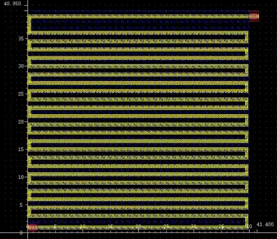
One thing to also take note of is that resistors in an IC layout are HUGE, compared to MOSFETs. And considering that high resistance values are recommended when using MOSFETs, they're kind of a waste of space too.
The first image is a 2 MOhm resistor and the second one is a CMOS Inverter in comparison.
 http://webpages.eng.wayne.edu/cadence/ECE6570/res/Layout_of_Resistor.htm
 http://pages.cs.wisc.edu/~david/courses/cs755/cs755/tutorials/tutorial3/tutorial3.html