4

I have ten devices that I need to connect in a loop so they can send data from one device to the next until it returns to the original device. The devices are about 5 inches apart.

They are all 5V UART signals (1M Baud). The 10 devices are connected to power and ground in a star topology. It is basically a circle with each device evenly spaced along the edge with the power coming from the center.

My question is, should each data signal be accompanied by a ground wire or should the power grounds be relied upon?

Having grounds with the data signal creates loops but not using grounds makes the data signal far from any ground increasing inductance.

I'm thinking it is better to not have the ground wires, but I don't know what the best practice is.
Alchitry
  • 143
  • 3
  • 3
    You should have ground wires with the data. These wires will be the return path for the high frequency of the signal. – Wesley Lee Sep 23 '21 at 23:27
  • 1
    Have you seen twisted wires before? that's to somewhat reduce the common mode induced noise (think 2 currents going the same dir'n, one from ground and one from power, and they cancel each other out). In my experience, only the data wire alone is somewhat "unreliable" if you will. – NeuroEng Sep 23 '21 at 23:36
  • 1
    If you don't have those return wires in place, how will the high frequency components of the signal return to the driver? They will take a very circuitous route through the star ground and power distribution network. The loop area of this path is much greater than the loop area formed by the signal+return configuration. The greater the loop area, the greater the inductance, which translates to higher noise, since V=L(di/dt). And the larger the loop area, the easier it is for radiated emissions to occur. – SteveSh Sep 24 '21 at 01:09
  • 1
    As the other commenters noted, you want to minimize the total loop area of (signal + return). But also ground loops are considered to be a Bad Thing. So you need to find a way to meet both these goals at once. You might be able to pull that off with single-ended comms, but if I were designing this circuit I'd just put in differential (maybe RS422) signaling -- the drivers and receivers are plentiful and cheap. Then you can stick with your star ground topology but still run your comms with nice small loop areas. – Mr. Snrub Sep 24 '21 at 08:25
  • Thanks for the input. I currently have it setup with grounds all around and haven't run into issues. A previous iteration actually used differential signals as it was the obvious way to solve both problems but the drivers, while cheap, added cost to the relatively cheap boards and seemed potentially unnecessary. – Alchitry Sep 24 '21 at 13:17
  • well at that distance usually ground loops are not a problem. usually the solution is bonding i.e. *fat big common ground strap*; also as already suggested differential transmission can be useful – Lorenzo Marcantonio Oct 06 '21 at 07:56

2 Answers2

1

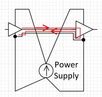
Like I said in my comments, you want the return to be in close proximity to the signal, which is what a ribbon cable or twisted pair does. Here are a couple of cartoons to illustrate the problem.

The first shows the current flow if you don't have a return with each signal. They take a very circuitous route through the star ground and power distribution network. The loop area of this path is much greater than the loop area formed by the signal+return configuration (see next picture). The greater the loop area, the greater the inductance, which translates to higher noise, since V=L(di/dt). And the larger the loop area, the easier it is for radiated emissions to occur.

enter image description here

The picture below shows the current flow when returns are provided with the signals. Note the smaller area of the loop, which mean lower inductance, and so lower voltage transients and lower radiated emissions.

enter image description here

SteveSh
  • 9,672
  • 2
  • 14
  • 31
0

I believe the answer is to have the ground wires (as largely stated in the comments) to minimize inductance/noise generated from the data signals.

Most of what I could find on ground loops pertains to earth ground (making HUGE loops) and analog systems. The digital signal being 5V means it can tolerate a decent amount of interference. The ground wire accompanying the signal has about 0.02 ohms of resistance which means you'd need 25A of induced current to shift the ground voltage by 0.5V (which would still be in the acceptable amount of noise).

Unless I'm missing something else, it seems I was worrying about the ground loops needlessly.

Alchitry
  • 143
  • 3
  • Well you're ignoring inductance and the rise/fall times of the currents. The DC resistance has little to do with this. – SteveSh Sep 24 '21 at 20:55