39

I'm confused again. Per various antenna dipole calculators online, and if GPS uses 1.575 and 1.228 GHz signals, the dipole antenna needs to be on the order of 10 cm. Yet Adafruit has (or had) tiny GPS antennas of about 9mm square. And there's the Apple watch that does GPS.

How does that work? The signal can't be in near-field conditions, not with the satellites living in orbit. Consider 100 MHz. The calculators will give a dipole antenna length around 1.5 m. Every stereo I've ever bought comes with a dipole antenna about same length as the calculators now predict. How can the Apple watch and the Adafruit antenna work with (I guess) antennas about 1/10 of what the calculators predict? I realize that different antenna geometries will give different results, but a factor of ten???

user3303210
  • 517
  • 4
  • 5

4 Answers4

68

Let’s start off with some antenna basics.

Antenna efficiency is proportional to the length of the antenna up to \$\frac{\lambda}{2}\$ where $$\lambda = \frac{v}{f}$$

An antenna that is half the length of the electromagnetic wave it is receiving is referred to as a “half wave” antenna. In free space, a GPS signal at 1.575 GHz has a wavelength of 19 cm, so a you would want a 9.5 cm half wave antenna to pick up the signal without efficiency loss from the antenna itself. Steve Jobs is rolling over in his grave right about now. You can’t put a 10 cm antenna in an iPhone! So what can we do to make it smaller?

To start off, you can trick the wave into thinking the antenna is actually half the wavelength by making it a quarter of the wavelength and then mounting it to an adjacent conductive ground plane or chassis that is also at least a quarter of the wavelength. This is referred to as a “quarter wave” antenna. For our GPS receiver, we would need a 4.25 cm quarter wave antenna to pick up the signal. Not quite good enough, but at least we’re going in the right direction! What else can we do?

Well let’s look back at our equation for \$\lambda\$. Is there a way we can make the wavelength shorter so we can have a shorter antenna? Well the frequency is set, there’s not much we can do to change it, but what about the phase velocity? Phase velocity is defined as $$v = \frac{1}{\sqrt{\epsilon \mu}}$$ where \$\epsilon\$ is the permittivity of the transmission medium, and \$\mu\$ is the permeability. If we can increase either of those, we’ve bought ourselves some length.

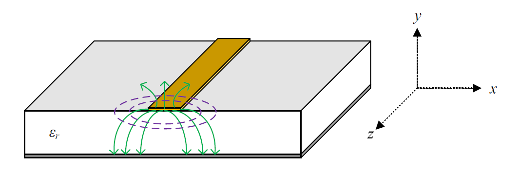
Well it turns out that most GPS antennas are microstrip antennas, so the wave travels partly through air and partly through the substrate of the PCB as shown in this picture.

enter image description here

https://www.3ds.com/uploads/pics/microstrip-transmission-line-quasi-tem-mode.png

Calculating the actual wavelength of the wave traveling on a microstrip is not very straightforward, but for example if we use FR4 as the PCB substrate, we might be able to reduce the wavelength by about half if we are lucky. Great, so we’ve gotten our antenna length down to ~2.1 cm. Is that good enough? Nope!

This is where things start to get a little hairy, and by hairy I mean nonlinear. Antenna designers have asked themselves what else they can do to make antennas smaller, and they found a very nifty trick. You can “slow down” the wave traveling in the microstrip by making a slot in the ground plane which forces the return current on the ground plane to take a longer path. This effectively reduces the phase velocity of the wave which means you can make the antenna much smaller until all the sudden bing bang boom it’s only 9 mm squared. Now that’s the kind of antenna phone manufacturers want to use!

There are other methods used to miniaturize antennas. There has been a lot of research centered around this idea, and as you can probably see, it gets pretty complicated. Complicated enough that most online calculators aren’t going to do the math for you.

Ryan
  • 2,189
  • 7
  • 17
  • 1
    Does the "length" of the antenna need to be along a straight line? Or is it possible to have more complex 2D or 3D shapes where the total length is what one wants, but the area covered has a much smaller side dimension? E.g. a spiral, or a back-and-forth shape, or...? Many of the smaller antennas (especially PCB traces) usually have weird shapes, is that for this reason? What about ceramic antennas? – jcaron Sep 16 '21 at 13:03
  • 4
    @jcaron this would be a separate question, but the simplest microstrip antenna topology is rectangular where the length determines the receiving wavelength and the width controls the impedance. There are other geometries used, including stacked and folded which would be 3D, but the goal of these is to increase the gain. Other types of antennas have different shapes to reduce the length and increase gain and bandwidth as well. – Ryan Sep 16 '21 at 14:26
  • 2
    I'm the guy who asked. Thanks very much. This explains what seemed impossible. Now I know I that the calculators are helpful but also what the calculators aren't taking into account. That's what I was after. – user3303210 Sep 16 '21 at 23:03
  • 1
    @jcaron Ceramics have a ridiculously high permittivity (dielectric constant), which is also why we use them to make caps. This high permittivity slows down the waves a lot, shortening the wavelength and thus the antenna as well. (But because ceramics are also way more lossy than air, the antenna isn't going to be as efficient as a grown-up one. But sometimes, size matters more than performance.) – TooTea Sep 17 '21 at 11:44
  • @jcaron Check out the Raspberry Pi 3 Model B or Raspberry Pi 4. It uses etched PCB antenna that has a fractal geometry. It's tiny – slebetman Sep 18 '21 at 05:41
  • 3
    Good balance between tech details, literary skills and formulae +1 – Andy aka Sep 18 '21 at 11:48
  • I came here to say what I see Andy has already said. – Russell McMahon Sep 22 '21 at 06:07
11

Physics sets no lower limit to the size of an efficient antenna. There are tradeoffs between efficiency, size and bandwidth: I've seen various approximate formulas that attempt to capture this. GPS has a low bandwidth, so the minimum size for an efficient antenna is small. In practice, the smaller the size of the antenna, the more that non-ideal material properties (resistivity, dielectric absorption...) affect the efficiency.

The common half-wave dipole is special only in the sense that it's simple to analyze, simple to build, and relatively insensitive to the properties of its materials. Design of smaller efficient antennas is a trickier business.

John Doty
  • 2,227
  • 5
  • 12
  • 2
    Perhaps consider using "effective" as in _fit for purpose_, instead of "efficient" as in _with minimal losses_. An antenna can be 2% "efficient", but still be "effective" in a receive-only, low-datarate application (specifically thinking of time signal receivers that fit in an alarm clock but receive the 1-baud 77.5 kHz DCF77 time signal from 2000 km away...) – Jostikas Sep 17 '21 at 15:16
  • @Jostikas True, to sense a signal you need not transfer power to the input amplifier. But part of the trick to sensing without power transfer while minimizing noise is having an amplifier with noise temperature well below the ambient electromagnetic noise temperature. At 77 kHz, the natural noise level is a trillion kelvin, so it's not too hard. At 1.5 GHz, natural noise is 3 kelvin or so: input amplifier noise dominates. If you're really fussy about GPS signal/noise the optimum won't generally correspond to perfect power transfer efficiency, but it will be fairly close. – John Doty Sep 17 '21 at 15:46
  • @John Doty: Perhaps incorporate some of this in the answer (comments may be deleted at any time)? You can [edit (change)](https://electronics.stackexchange.com/posts/586993/edit) your answer. (But ***without*** "Edit:", "Update:", or similar - the answer should appear as if it was written today). – Peter Mortensen Sep 19 '21 at 13:22
  • @PeterMortensen The comment addresses Josikas's comment, not the original question, so it doesn't belong in the answer. – John Doty Sep 19 '21 at 15:45
  • @JohnDoty Okay, now I'm curious. The "natural noise" -- where does that come from? I've been poking around on Wikipedia and such, and I can't figure out how you get those numbers. Can you give me a reference for that? or what I should google? I see equations for band width, but that's not the same thing as frequency, of course. – user3303210 Sep 20 '21 at 19:22
  • For frequencies below 30 MHz, it's a mostly a combination of atmospheric (lightning) and galactic (synchrotron) noise. CCIR Report 322 (https://search.itu.int/history/HistoryDigitalCollectionDocLibrary/4.276.43.en.1008.pdf) is the standard reference. From ~30 MHz to ~1 GHz, galactic noise dominates. Other cosmic sources, including the Sun, contribute a bit, too. Above ~1 GHz, the 2.7 kelvin cosmic background from the Big Bang dominates. – John Doty Sep 20 '21 at 19:42
  • @John Doty My comment was mainly a linguistic one. – Jostikas Nov 17 '21 at 12:56
  • @Jostikas Then I stand by what I wrote. It's common to have small antennas that are *effective* at reception but not *efficient*, especially at lower frequencies. But for microwaves, effectiveness and efficiency are more closely related. – John Doty Nov 17 '21 at 13:29
  • @JohnDoty You mention bandwidth - does it boil down to it being a "small antenna can be efficient, but for a very narrow range of frequencies" situation? So a GPS antenna for a C/A code receiver can be efficient, as its only ever expected to receive 1545.72 +-0.5 MHz, while something like a miniature BLE antenna loses out due to being expected to perform roughly equally well across it's 80 MHz range of potential frequencies? – Jostikas Nov 24 '21 at 06:32
  • @Jostikas Yes, that's it. – John Doty Nov 24 '21 at 12:53
7

The signal can't be in near-field conditions, not with the satellites living in orbit.

Ferrite rod antennas in AM radios operating from 150 kHz to around 1700 MHz were nowhere near the dimensions of the propagating wavelength. They just used the presence of one part of the EM wave to pull a signal from the "ether": -

enter image description here

Picture from this question and answer. Onward link available.

The ferrite rod picks up on the magnetic (M) part of the EM wave.

They're not quite as effective as a dipole or monopole but they are "good enough".

I'm not saying that your unspecified and vague GPS antenna operates on this principle but, that the above technique can be re-scaled for higher frequencies.

Andy aka
  • 434,556
  • 28
  • 351
  • 777
  • `+1` for best answer and for using an AM radio to do it. Although it's a suboptimal example for the present question, [resonant inductive coupling](https://en.wikipedia.org/wiki/Resonant_inductive_coupling) for wireless charging illustrates the "pulling-in of an AC magnetic field from the 'ether'". It's a case where power efficiency should be high, and since it is in the near field it can be very high compared to geometrical. (e.g. [WiTricity](https://en.wikipedia.org/wiki/WiTricity)) – uhoh Sep 18 '21 at 10:02
5

Who's to say one needs a very efficient antenna?

Old days - one needed an active antenna (puck) to get almost any function at all. While a better antenna is always a goal, they aren't always needed for reasonable performance. The fancy hardware and math that generates the huge processing gain under the hood is responsible for much of the performance.

mike65535
  • 1,481
  • 2
  • 16
  • 26