2

Following my previous question, I came up with the following circuit using 74HC123 for simulation and in practice planning to use this IC. The circuit out should be ON when it waits for a rising edge for more than a time determined by R1 and C1. Hence the output will turn ON when there is a pulse missing(pulse freq is 3MHz):

enter image description here

And the time plots for the input pulse train and the output is shown below. As you see the output turns on after a time from the the last rising edge determined by R and C:

enter image description here (left-click to view better)

But now at the very beginning the output turns on as well which I don't want it in real. Can there be a remedy for that? I don't want the relay to turn ON at around time zero when the circuit is powered.

The only thing comes to my mind(which is manual) is to couple the out to a relay after the circuit is powered(?)

Edit 2:

First circuit from Simon Fitch with AND gate and RC:

enter image description here

enter image description here

enter image description here

I also had to set "Skip initial operating point solution" in LTspice.

GNZ
  • 1,559
  • 4
  • 25
  • 52
  • 3
    There were no pulses prior to the first one, so the output of the missing pulse detector being high at the start is technically correct. But if you want to have a "startup lockout" function, you'll need a separate circuit that identifies the startup conditions and triggers a separate timer for the lockout period. – Dave Tweed Sep 10 '21 at 11:35
  • How about my last sentence? Would that a poor remedy? – GNZ Sep 10 '21 at 11:36
  • No, that's what I'm talking about. But you'll have to provide a lot more detail about your specific application. For example, you refer to "a relay". If that's an actual electromechanical relay, keep in mind that its response can be measured in milliseconds, while the missing pulse detector reacts in nanoseconds. Start-up may be a non-issue. – Dave Tweed Sep 10 '21 at 11:38
  • Are you saying that mechanical relay(interfaced with a transistor and a diode) might not turn ON for ns durations? I could then lock/latch the output ON forever right after the first missing pulse(not the one at start up)? – GNZ Sep 10 '21 at 16:24
  • It's impossible for me to say, since you haven't given any details about what it is you're trying to accomplish here. What is the application for this circuit? – Dave Tweed Sep 10 '21 at 17:37
  • I just want to shut down the main power supply to a system whenever a single missing pulse occurs. – GNZ Sep 10 '21 at 17:48
  • 2
    I think the last sentence is a good start, but can probably get away with simple digital logic instead of using analog switching. Maybe just a 2-input AND gate with the other input being an RC-delayed version of VCC. Might need Schmitt trigger version of the gate if the RC is slow enough. – Ste Kulov Sep 11 '21 at 03:42
  • You have an active low Reset that you have hardwired to Vcc. Add resistor and capacitor to provide power-on reset. – StainlessSteelRat Sep 19 '21 at 15:03
  • @GNZ In place of a 7408 (AND gate), use a Schmitt trigger NAND gate 74132 (or old half 7413) gate followed by an inverter (other gate 74132 or half 7413). The R2-C2-74132 will work cleaner as stated just before. – Antonio51 Sep 20 '21 at 03:26

3 Answers3

5

The trouble with using \$\overline{Q}\$ as the main output is that you rely on the monostable being triggered as soon as power is applied, to bring \$\overline{Q}\$ low. Then you keep retriggering as the leading edge of each input pulse arrives.

You may get lucky, and have the device power-up in a triggered state, as explained in "11.2 Power-up considerations" on page 13 of the Nexperia datasheet. Otherwise though, if the 74'123 starts in an untriggered state, \$\overline{Q}\$ will be high at power-on, and the only way to automatically trigger the monostable (bringing \$\overline{Q}\$ low) will be to provide some trigger signal as soon after power-on as possible.

For this reason, \$\overline{Q}\$ will require external gating, if you wish to guarantee a low output at power-on, like this (I don't show timing elements \$R_{EXT}\$ and \$C_{EXT}\$, to keep it clear):

schematic

simulate this circuit – Schematic created using CircuitLab

C1 and the AND gate ensures that OUT stays low for a period of approximately \$R1 \times C1\$ seconds after power is applied. D1 discharges the capacitor immediately upon power-off, and prevents a negative voltage at the top of C1 from damaging the AND gate input. D1 may not be necessary if the AND gate already has input protection diodes.

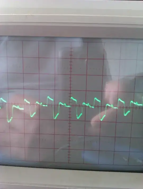
A second problem you may encounter is that the output \$\overline{Q}\$ will go high only until the next incoming pulse. If the pulse is only a little late, then you may find that the output will go high for mere nanoseconds. On page 11 of the TI document "Designing with the 74LS123", they have a "missing pulse detector" circuit which uses both monostables of the 74'123 to overcome this problem. They use the second unit to provide a fixed-length pulse, regardless of the duration of the output pulse of the first unit:

enter image description here

This circuit has the fortunate side-effect of eliminating the problem of an initial high output, because it relies on the falling edge of OS1's Q output to trigger the second unit OS2. You use OS2's Q output, which you know will be low at power-up.

It still suffers from the ambiguous start-up state, but this can be solved with another RC power-on delay to force both units to start up in the untriggered state, as described on page 13 of the Nexperia datasheet:

schematic

simulate this circuit

The above solution also requires only a single IC, which is a bonus. You mentioned activating a relay, so this above solution will also permit you to activate it for some known, controlled period of time, independent of the duration of the detected anomaly.

Simon Fitch
  • 27,759
  • 2
  • 16
  • 87
  • I simulated your first circuit and no difference. Cannot get rid of the initial pulse. I will go through other suggestions and update here during the week. Do you have any SPICE simulator? Cant you just simulate the first one and see whether it works for you? I read answers but when it comes to simulation all failed until now. – cm64 Sep 14 '21 at 18:46
  • @cm64 In the original the initial high \$\overline{Q}\$ output is due to the monostable being untriggered until the first pulse arrives, but the only reasons I can think of for that AND gate output to go initially high are: a simulation artifact, capacitive feed-through of an infinitely-fast rising Vcc, undefined behaviour as the power supply rises to 5V, or R1xC1 being shorter than the period of incoming pulses. How long does your simulated initial high output last? – Simon Fitch Sep 14 '21 at 23:02
  • @cm64 Without very accurate models of the 74LS123 and AND gate, and a realistic rise time on Vcc, simulation cannot reveal realistic initial behaviour. I am confident that the AND gate output cannot possibly be high for longer than a few nanoseconds after Vcc has settled. Behaviour prior to Vcc becoming stable and within the working parameters of the devices, you cannot have any guarantee of the behaviour of any logic element, real or simulated. – Simon Fitch Sep 14 '21 at 23:19
  • When I set "Skip initial operating point solution" in LTspice, your first circuit with AND gate worked. No more initial trash. See my Edit 2 for simulations. – GNZ Sep 15 '21 at 16:48
2

NEW EDIT :

I think monostables are quite susceptible to noise and parasitic impulses. They should therefore be avoided as much as possible for safety reasons. If a simple circuit may be suitable, as proposed in one of the answers, a "FSM" or counter system ... (for pleasure as an exercise or for reasons of choice), for example, could also be used. I am thinking of a prepositioned counter (when starting up) which would count or count down at each clock stroke (10 MHz). The 3 Mhz signal would be used to ensure the direction of "counting". The up / down counter would then be positioned around the pre-positioned "average" value. When the 3 MHz signal (duty 50%) disappears (long 0), it would continuously count down (or up) and as soon as it reaches zero (or 0xF), it triggers the "missing input" signal.

Example of circuitry without "monostable" ... schematic + behavior.

enter image description here

enter image description here

Here is what you can do for eliminating the starting pulse ... Add only reset circuitry.

https://assets.nexperia.com/documents/data-sheet/74HC_HCT123.pdf figure 14

enter image description here

EDIT : Be carefull for "k-map behavior" of this retriggerable monostable. A bit "complicated".

Seems not be very effective ! See k-map, last line !

enter image description here

EDIT : As stated by @Dave Tweed in his comment ...

What is advised by TI for "missing pulse detector" : https://www.ti.com/lit/an/sdla006a/sdla006a.pdf?ts=1631458202807&ref_url=https%253A%252F%252Fwww.google.com%252F

I have not tested, to be simulated, I am not sure.

enter image description here

Edit 2:

enter image description here

enter image description here

enter image description here

I also had to set "Skip initial operating point solution" in LTspice.

Antonio51
  • 11,004
  • 1
  • 7
  • 20
  • Does it mean I just need to add R and C for the rest pin? I tried that with different values in sim, it didnt work. – GNZ Sep 13 '21 at 09:02
  • Yes. only add R and C. But problem ? I did not see any value for these components ... Only the fact that it is no input with Schmitt trigger. ("Schmitt-trigger action on all inputs except for the reset input"). So try with a resistor ~ 1k as TTL circuit. R*C perhaps of 100 us ... So C=100us/1000 = 0.1 uF (unless error). I investigate to see if this is enough. – Antonio51 Sep 13 '21 at 09:48
  • What i have found is this note about. I hope this will help. I am reading it ... https://www.ti.com/lit/an/sdla006a/sdla006a.pdf?ts=1631458202807&ref_url=https%253A%252F%252Fwww.google.com%252F – Antonio51 Sep 13 '21 at 10:18
  • Sorry. Nothing seen about these components in this note. If necessary, add a Schmitt-trigger (74LS13 or 74LS14 or 74LS132) gate which will make a clean forced reset at power-on – Antonio51 Sep 13 '21 at 10:37
  • I need answer that works and shown at least by simulation. I already tried these I cannot get rid of(skip) the first(initial) pulse. – GNZ Sep 13 '21 at 14:09
  • 2
    @GNZ If you're expecting a simulation to tell you the exact real result, your expectations are too high. Any simulation will be only as good as the models within. This model, in particular, is made with LTspice's own A devices, which do not have a power supply -- they generate the output as needed. This is why your simulation will not show the result in the datasheet. Antonio's answer is on point and the simulation will not show the real result. I would warmly suggest you take this to a breadboard, not a simulation. Hint: nobody says you have to test it with ns pulses. – a concerned citizen Sep 13 '21 at 14:45
0

I don't want the relay to turn ON at around time zero when the circuit is powered.

The only thing comes to my mind(which is manual) is to couple the out to a relay after the circuit is powered(?)

  1. A few nano seconds (30 or 40nS delay) of pulse will not trigger any relay. The real question is how soon a trigger signal can be supplied after power on. And, the powering is not going to be a unit step. You will need reset circuitry.

  2. The operations of your signaling circuitry has to be established before any power control (relay-ed) circuitry gets powered. Reset and power sequencing is needed.

Can there be a remedy for that?

"Reset" puts a system in a "known state". From a proper reset circuitry, generate system wake-up sequence (power sequence). Gate the relay drive signal using the reset signal or from the wake-up sequence.

Meantime, you need to find a different HC123 model that has power pins, so you can simulate power on sequence correct. However simulated/tested, a circuitry that 'relies on the uncertain/undefined/unstable state is not 'reliable.

While "Incorrect" is a problem, your problem is incorrect (??).
Q is high pulsed at trigger signal, and Q# is other way around. And, Q & Q# are expected to be at reset state on power up, which is correct, which is the state before HC123 can see the trigger signal. Meantime, what you try to find is "no trigger, no signal".

jay
  • 3,781
  • 8
  • 24