You need to do two things:
- Shift output down by a volt so that it's 0V-3V.
- Scale the output from 0V-3V by multiplying the thing by 5/3.
For that we can use op amp as differential amplifier.
Here is the article I used, you don't really need anything else: link
Schematic:
From the same article, we'll simplify the thing a bit. If R1=R2 (because we are lazy and why the hell not),
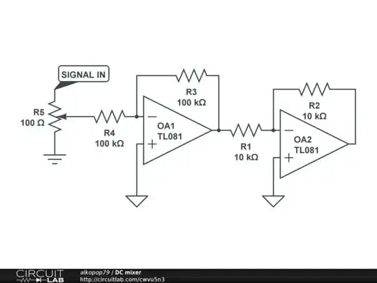
Where you want V2 to be your sensor output and V1 is your 1V voltage reference. That is your difference, that is where you subtract 1V. Then you need to multiply it by 5/3, which is just a relation between the resistors in the very same formula.
P.S. you may want to have sensor output buffered with op amp voltage follower, because the subtractor circuit will pull current directly from the sensor, which is not good for accuracy if the current is large enough, check sensor specs for how much current it can source, if it sources enough, you can get away without buffer - given correct magnitude of resistors; same for 1V reference. Resistors should be in kiloohms or dozens kiloohms in my opinion, then you probably will do ok without buffers.
EDIT
Circuitlab simulation confirmed my circuit for sensor values of 1V, 2.5V and 4V (output 0V, 2.5V and 5V). Can't share it because I'm a freeloader, but you're welcome to replicate my circuit there and see for yourself.