0

I’m very desperate to solve this problem so any advice is greatly appreciated.

I got a deal on a 9A corded drill and took it apart today after testing to make sure it has enough power to do what I need it to do (it does)

I ordered a relay with a 10A capacity and forward and reverse functionality( crucial for my application) and when I went to take the drill apart I found more wires than I thought there would be. (I’ll link pictures at the end)

Some quick research shows that blue is often used as a neutral wire so my questions are.

  1. safe to assume that blue is neutral in This case?

  2. my relay has reverse, common and forward. Where I thought hot /neutral would be. What do these mean?

  3. If blue is neutral, do I tie them all together and then terminate at the relay?
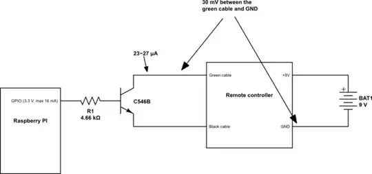
Relay
Relay

the drill wiring
the drill wiring

circuit diagram on the trigger relay

jsotola
  • 2,497
  • 2
  • 12
  • 21
  • 2
    `safe to assume` ... never assume anything – jsotola Aug 30 '21 at 23:19
  • 1
    It's probably using a universal motor. To reverse it you would switch the polarity of either the rotor or the stator windings (but not both). So, you might need 2 relays. I'm not sure what kind of motor that relay is intended to work with? – Drew Aug 30 '21 at 23:48
  • does the other side of the trigger assembly have a diagram? – jsotola Aug 31 '21 at 00:00
  • what's the diagram on top of the trigger assembly? – jsotola Aug 31 '21 at 00:12
  • The switch behind the trigger - is that the forward/reverse switch? – Pete Hooper Aug 31 '21 at 00:16
  • 1
    @PeteHooper I think that the direction switch is the gray lever in the middle picture ... it operates the top section of the trigger assembly ... the reversing magic happens there ... there is a diagram on top – jsotola Aug 31 '21 at 00:22
  • @jsotola you’re probably right. I’m having difficulty wrapping my head around these parts when they aren’t in a casing. – Pete Hooper Aug 31 '21 at 00:32
  • @PeteHooper the yellow button on the side is probably the trigger lock ... or either prevents the trigger from being pressed, or it latches the trigger in the ON position – jsotola Aug 31 '21 at 01:38
  • @jsotola yea assuming is never right so good call – Jordan Isaacson Aug 31 '21 at 12:56
  • I think this motor is over my head, I know very very basic things about motors and electricity. Might have to just return this one and try something else. – Jordan Isaacson Aug 31 '21 at 12:56
  • if there is a diagram on the other side of the switch, then post it please ... also post a picture of the top of the switch ... it appears that there is a diagram there – jsotola Sep 04 '21 at 00:51
  • this appears to be identical to yours ... https://electronics.stackexchange.com/questions/167556/how-does-the-circuit-of-a-basic-variable-speed-electric-drill-work – jsotola Sep 04 '21 at 00:58

0 Answers0