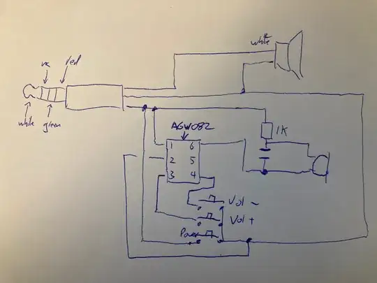
I am trying to use this mobile compatible handpiece for a non mobile phone project and wanted to be able to use the 3 buttons on it. It has a power button, Vol - and Vol +
I've traced the schematic. Most of it seems to follow the following I found for decoding button on a phone headset (here the buttons are Play/Pause, next and previous: https://stackoverflow.com/questions/53877830/get-input-of-switch-control-via-headphone-jack-on-ios). The idea is it relies on putting a low resistance across the microphone.
When I press the power button, it shorts it, so that's like the play/pause button. all good here. But I am stumped with the Vol+ and Vol-. They go into the chip marked 'AWG082' which I can't find any info for.
If I measure the resistance across the microphone, then it's 16k with nothing presssed, 1 ohm when I press the power, and 16k (not changing) when I press the vol- and vol+ buttons.
So...
- Any idea what that chip is?
- Am I getting no resistance change across the red and green terminals when I press the vol+/vol- because the chip actually needs power, and power would be provided to the red terminal to power the microphone? if so, what voltage should I put there?
thanks

